Objective
The objective of this activity is to understand the basic concept of active mixers.
Background
A mixer is a three-port device that can modulate or demodulate, and can either be passive or active. The main function of a mixer is to change the frequency of a signal while preserving every other characteristic of the initial signal. What differentiates an active mixer from a passive mixer is that an active mixer employs active devices to apply conversion gain.
The output of a mixer can be of two forms, as shown in Figure 1. The mixer accepts two frequency inputs and delivers one frequency output. The output, as shown in the diagram, can either be the sum or the difference of the two input frequencies. These frequencies can be identified as the following: local oscillator (LO), radio frequency (RF), and intermediate frequency (IF).


Mixers are mainly used to perform frequency conversions that can be classified as upconversion and downconversion. The LO port is always an input port unlike the RF and IF port, which can either be an input or output depending on the application. In a downconversion mixer, the other input port is the RF port, and the output is at a lower IF as shown in Figure 2a.


In an upconversion mixer, the other input is the IF, and the output is the RF signal as shown in Figure 2b.
Materials
- ADALM2000 Active Learning Module
- Solderless breadboard and jumper wire kit
- Two 1 kΩ resistors
- Two 6.8 kΩ resistors
- One OP37 precision op amp
- One LTC1043 precision switched-capacitor block
- Three N-channel MOSFETs (2-ZVN3310, 1-ZVN2210A)
Single-Balanced Active Mixer
Mixers can also be classified as a single-balanced mixer and a double-balanced mixer; each has its own advantages and disadvantages.
A single-balanced mixer, often called a balanced mixer, is a type of mixer that suppresses either the LO or RF signal but not both. This configuration is hardly used because of its susceptibility to noise in the input LO signal. The main drawback is its IF-LO feedthrough, which means the LO signal can leak into the IF signal if the IF signal frequency is not much lower than the LO signal frequency. A simple circuit of a single-balanced mixer is shown in Figure 3.


Hardware Setup
Build the following breadboard connection shown in Figure 4.


Procedure
Use signal generator W1 and W2 as the frequency inputs to the mixer. For the LO frequency, use W1 and set it to 5 V, 210 kHz sine wave. For the RF input, use W2. For the upconversion mixing, W2 should be lower than the LO frequency, so set W2 to 5 V, 25 kHz sine wave. The expected output is at 185 kHz and 235 kHz. Analog Ch2 monitors the RF input, W2, whereas Ch1 monitors the IF output through the spectrum analyzer. The result is shown in Figure 5a.


For the downconversion mixing, set W2 to 5 V, 260 kHz sine wave; this will serve as the RF input to the mixer. The expected output is at 50 kHz, and the spectrum result should look like Figure 5b.
Single-Balanced Active Mixer Implemented with the LTC1043
Background
Ideally, to meet the low noise, high linearity objectives of a mixer, we need a circuit that implements a polarity switching function in response to the LO input. Thus, the mixer can be reduced to Figure 6, which shows the RF signal being split into in-phase (0°) and antiphase (180°) components; a changeover switch, driven by the LO signal, alternately selects the in-phase and antiphase signals. Thus, reduced to essentials, the ideal mixer can be modeled as a sign switcher.


Simulation
For a demonstration of the mixing concept, we can use the ideal switching mixer shown in Figure 6. The mixer can be built with the LTC1043 CMOS analog switch, which is a monolithic, charge-balanced, dual switched-capacitor instrumentation building block. A pair of switches alternately connects an external capacitor to an input voltage and then connects the charged capacitor across an output port. An internal clock is provided, and its frequency can be adjusted with an external capacitor. If no capacitor is connected at pin Cosc, the internal oscillator will have a frequency of 210 kHz. With a 39 pF external capacitor (smallest value from the parts kit), the internal oscillator of the LTC1043 will have an 80 kHz frequency. Simulations were performed for the configuration with no capacitor connected at Cosc.
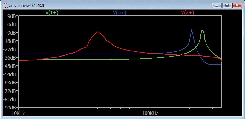
Figure 7 shows the circuit in LTspice®, but it can be implemented with hardware parts on a breadboard. We use the inputs of the first switch of the LTC1043. The input signal will be generated on Channel 1 of the signal generator and connected to S1A. To obtain its inverted version we build a simple inverting amplifier with unity gain and connect it to S2A. The output is visualized at pin CA+ with Channel 2+ of the oscilloscope. For a downconversion mixer, Channel 1 of the signal generator must be set at a frequency higher than that of the oscillator—for example, 250 kHz. The output will be the difference of the two frequencies at 40 kHz. See Figure 8.


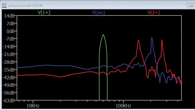
If Channel 1 of the signal generator will be set at 60 kHz, the output will have two components (one at fLo + fin = 270 kHz and one at fLo – fin = 150 kHz). See Figure 9 for the upconversion FFT analysis.

Double-Balanced Mixer or Gilbert Cell
Double-balanced mixers are mainly used to avoid the LO product terms from the output signal. This configuration requires two single-balanced mixer circuits with two differential RF transistors that are connected in parallel and provides an anti-parallel switching pair. The LO product terms are canceled out and the RF signal is doubled at the output signal. This configuration produces a high degree of isolation between LO and IF, which eases the filtering requirements used after mixing the signal. For noise, these mixers are less susceptible than the single-balanced mixers because of the differential RF signal. This mixer is also known as the Gilbert cell. See Figure 10.


As observed in the circuit, there is a lot of symmetry of the Gilbert cell mixer. This enables the balance to be obtained and the rejection of the LO and RF signals at the output. The Gilbert cell is not as widely used within systems using discrete components because the number of components required is high. However, for integrated circuits, Gilbert cell mixers are ideal because the number of components is not particularly important; they do not require wound components like transformers or other inductors, and they are able to offer a high level of performance.
LTspice Simulation
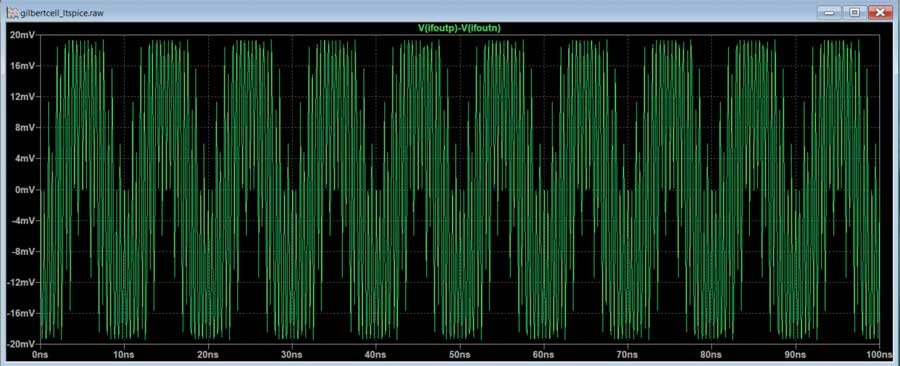
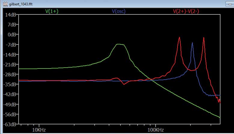
Since the component provided in the kit is not enough to construct the circuit, let’s instead simulate the circuit in LTspice. The LTspice files for simulation can be downloaded from theLTspice Education Tools on GitHub. Figure 11 shows the IF output of the circuit. We took the difference between the positive and negative IF output.

Double-Balanced Active Mixer Implemented with the LTC1043
The double-balanced mixer configuration requires two single-balanced circuits. We can build this configuration with the LTC1043 as it has many switches, and it provides the antiparallel switching pair needed. Figure 12 shows the schematic of the circuit. The circuit and the connections are almost the same—only the inputs of the second switch (S3A, S4A) are connected in reverse order to the inputs of the first switch (S1A, S2A). In this case, the output is visualized with oscilloscope Channel 2+ at pin CA+ and 2– at pin CA–.


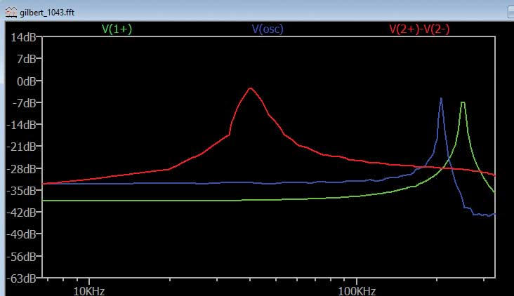
To analyze the downconversion configuration, on Channel 1 of the signal generator is a sine wave with 250 kHz frequency and 1 V amplitude peak-to-peak. See Figure 13 for the resulting FFT analysis.

For upconversion, the sine wave generated on Channel 1 will have a frequency smaller than that of the LTC1043 internal oscillator— for example, 50 kHz. The FFT analysis for this frequency value is seen in Figure 14.

Questions
- What is the main advantage of using a double-balanced mixer (Gilbert cell) over a single-balanced mixer?
- What role does the LTC1043 play in the implementation of an active mixer?
You can find the answers at the StudentZone blog.
