Objective:
The objective of this lab activity is to:
- Measure component impedance and circuit impedance using the ALICE-VVM Impedance Analyzer software.
- Study the magnitude and phase changes with change in frequency for an RLC circuit.
Background:
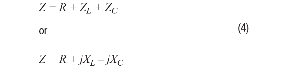
Impedance is the resistance to the flow of alternating current. It is the total opposition that a circuit offers to the flow of current at a particular frequency. Impedance (Z) is expressed as a combination of resistance (R) and reactance (X) and is measured in ohms (Ω). It can be expressed as a complex quantity as:

The impedance is represented on a 2D polar plot that has x as its real axis and y as its imaginary axis. The resistive component is a line along the real axis and the reactive component is a line along the imaginary axis.
For a resistor, the impedance is the same as the dc resistance and is a line along the x-axis. For a capacitor, the impedance (or more specifically, the reactance) XC is imaginary and is represented as a line along the negative y-axis of the 2D polar plot. The reactance of the capacitor depends upon the frequency and is given as:

Where ω = 2πf is the angular frequency.
For an inductor, the impedance (or more specifically, the reactance) XL is imaginary and can be represented as a line along the positive y-axis of the 2D plot. The reactance of the inductor also depends upon the frequency and is given as:

The impedance of a series RLC circuit is the sum of the impedances of respective components.
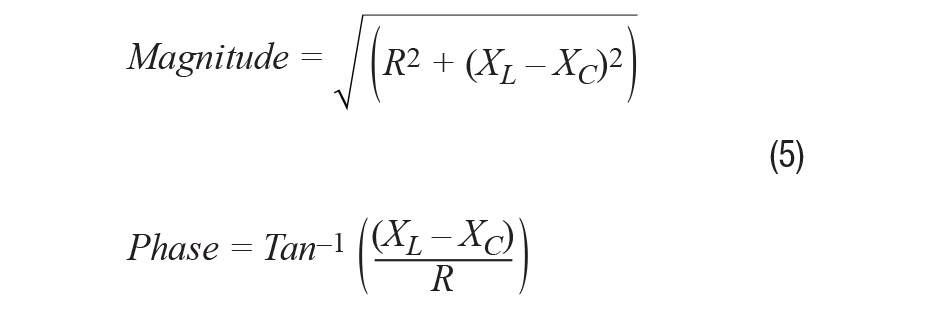
This can also be represented as a phasor vector on a polar plot with:


Materials:
- ADALM1000 hardware module
- Resistors (1.0 kΩ, 470 Ω)
- Capacitor (1.0 μF)
- Inductor (10 mH)
Procedure:
- Measurement of component impedance:
- With a resistor REXT = 1 kΩ connected between CA-V and CB-V, connect a 470 Ω resistor as RS between CB-V and the fixed 2.5 V supply.
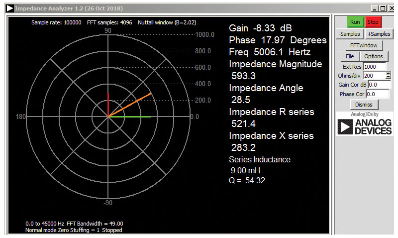
- Run the ALICE-VVM software tool.
- Note down the magnitude, phase, resistance, and reactance for the resistor in the table shown in Table 1. Note that the default frequency is set to 1000 Hz. Verify that the phasor is along the real axis and that the phase is zero. Also, the magnitude should be the same as resistance since the reactance is zero.
- Replace RS with CS = 1.0 μF and note the magnitude, phase, resistance, and reactance values. For the capacitor, the phasor should be along the negative imaginary axis and the phase should be +270° or –90°.
- Replace CS with LS = 20 mH. Note the magnitude, phase, resistance, and reactance values. For the inductor, the phasor should be along the positive imaginary axis and the phase should be 90°.
- Measurement of circuit impedance and effects of frequency on the RLC circuit:
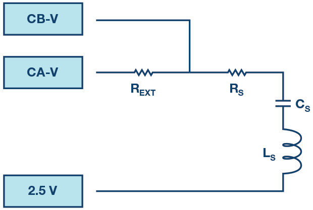
- Set up the series RLC circuit shown in Figure 1 with the given component values: REXT = 1 kΩ, RS = 470 Ω, CS = 1.0 μF, and LS = 20 mH.

Figure 3. Impedance measurement breadboard circuit. - Note down the magnitude, phase, reactance, and resistances for the RLC circuit at the default frequency of 1000 Hz. Record the values in Table 1.
- Adjust the frequency until the phase becomes zero and note this frequency. This is a special frequency where the total reactance is zero and the circuit is purely resistive.

If:

Then:

Thus, the impedance of the RLC circuit is now just the resistance. The frequency at which this occurs is called resonant frequency. It can be mathematically derived using Equation 9 to be:

- Vary the frequency below fo in steps of 100 Hz and take up to three measurement readings from the impedance analyzer. Record the readings in Table 1. Repeat the same by varying the frequency above fo in steps of 100 Hz. Carefully observe the rotation of the magnitude phasor (orange line).
- Set up the series RLC circuit shown in Figure 1 with the given component values: REXT = 1 kΩ, RS = 470 Ω, CS = 1.0 μF, and LS = 20 mH.

Measurements:
| Frequency (Hz) | Magnitude (Ω) | Phase (degrees) | Resistance (Ω) | Reactance |
Questions:
- Compute the resonant frequency fo for the series RLC using Equation 9 and compare it to the measured value. What is the percentage error between the two?
- Compute the magnitude and phase for the series RLC circuit, when the reactive component equals the resistive component.
You can find the answers at the StudentZone blog.
Notes:
As in all the ALM labs, we use the following terminology when referring to the connections to the ADALM1000 connector and configuring the hardware. The green shaded rectangles indicate connections to the ADALM1000 analog I/O connector. The analog I/O channel pins are referred to as CA and CB. When the hardware is configured to force voltage/measure current, -V is added, as in CA-V. When it is configured to force current/measure voltage, -I is added, as in CA-I. When a channel is configured in the high impedance mode to only measure voltage, -H is added, as in CA-H.
Scope traces are similarly referred to by channel and voltage/current, such as CA-V, CB-V for the voltage waveforms and CA-I, CB-I for the current waveforms.

