Objective
The objective of this activity is to use the principles of magnetic field generation and detection to build a simple proximity detector and observe how the detector output voltage increases as the electromagnet moves closer to the sensor.
Background
A simple proximity sensor senses how close one object is to another and can be used for many applications ranging from simple detection of open and closed doors and windows to sophisticated high precision absolute position detectors. They can be designed in several ways, one of which involves sensing the magnetic field strength generated by a magnet (often a permanent magnet but may also be an electromagnet). In this lab we generate the magnetic field using a ferrite-core solenoid. A solenoid is a coil of wire that is wrapped in a cylindrical fashion around a core (typically to fabricate an inductor with a particular value of inductance) or an electromagnet.
The 100 μH inductor contained in the ADALP2000 Analog Parts Kit can be used to generate a magnetic field that is strong enough to be detected by the AD22151 magnetic field sensor, also contained in the Analog Parts Kit. The AD22151 is a linear magnetic field transducer. The sensor output is a voltage proportional to a magnetic field applied perpendicularly to the package top surface. The AD22151 magnetic field sensor operation is based upon the Hall effect. The Hall effect is a phenomenon in which a voltage (the Hall voltage) is developed across a material when current flows through the material with a magnetic field present. The Hall voltage is due to the electric field produced by deflection of the moving charges by the magnetic field via the Lorentz force.
Materials
- ADALM2000 Active Learning Module
- Solderless breadboard and jumper wire kit
- Four 100 Ω resistors
- One 100 μH inductor
- One AD22151 magnetic field transducer
- Two 470 Ω resistors
- One 100 kΩ resistor
- One 0.1 μF capacitor
- One 10 μF capacitor
- One 200 kΩ resistor
- One LED
Hardware Setup
Start with building the electromagnet circuit presented in Figure 1 on the solderless breadboard.

Add the Hall effect sensor circuit with the AD22151 magnetic field transducer (Figure 2) to the solderless breadboard.

The breadboard connections are shown in Figure 3.

Procedure
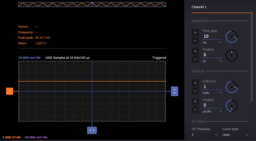
Use signal generator W1 to generate a constant 5 V signal as the VCC input of the AD22151. Turn on the positive power supply V+ to 5 V to power the electromagnet. The output of the AD22151 will be visualized on Channel 1 of the oscilloscope with the electromagnet far from the chip and no magnetic field present near the sensor.
This voltage corresponds the zero gauss point and is ideally midsupply, which is 2.5 V on a 5.0 V supply, but it will differ from midsupply due to DC offsets in the sensor and op amp that get multiplied by the op amp closed-loop gain.

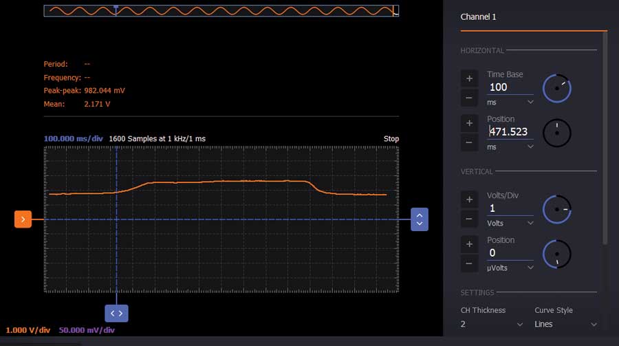
If the electromagnet is closer to the chip, the output voltage will increase proportionally to the magnetic field present. In Figure 5 you can see how the voltage increases when the electromagnet is close to the chip. When the electromagnet is farther from the chip, the voltage will decrease again until it reaches the zero gauss offset voltage.

The output offset voltage may be changed by adding a resistor, R4, between the 5.0 V supply and the op amp summing node on Pin 6. The objective is to place the sensor output voltage with no applied magnetic field as close as possible to the lower end of its linear range. We calculate the value of R4 in the next few steps.
We will designate VCC as the supply voltage of the AD22151 and VMID as the midsupply voltage.
Measure VCC using the voltmeter tool on Channel 2. To calculate R4 it is necessary to know the currents flowing in and out of the op amp summing node. The current through R2 is defined as IR2. Under ideal conditions this current would be zero since the voltage on each side of it would be VMID, but there is a small offset voltage between the internal Hall effect sensor output voltage with zero field and the internally buffered VREF. For small gains this voltage can in many instances be ignored, but it must be considered in high gain circuits such as this one.
Use the voltmeter to measure and record the voltage at Pin 7 and define it as VREF. Measure and record with the voltmeter the voltage at Pin 6 and define it as VCM; this is the common-mode voltage at the op amp input and is driven to be very close to the output of the internal Hall effect sensor by negative feedback. Calculate the voltage across R2 as:
VR2 = VREF – VCM (1)
and the current through R2 as:
IR2 = VR2/235 Ω (2)
The current through the feedback resistor R3 can be calculated taking into consideration the output voltage of the sensor with the electromagnet far from the chip, corresponding to the zero gauss point of the sensor. Define this voltage as VOUT,Z and compute the current as follows:
IR3 = (VCM – VOUT,Z)/100 kΩ (3)
Calculate the amount of voltage shift necessary to move VOUT,Z from its current level down to a lower level, in this case 0.5 V. Note that this is a negative quantity and is computed as:
VSHIFT = 0.5 V – VOUT,Z (4)
The amount of additional current, ISHIFT, required through the feedback resistor R3 to shift VOUT,Z to 0.5 V is computed as:
ISHIFT = VSHIFT/100 kΩ (5)
Note that this is a negative quantity because VSHIFT is negative. The current flowing into the summing node through R4, IR4, that is used to create the desired offset is in the opposite direction to that of ISHIFT, so we can write IR4 = –ISHIFT, which is a positive quantity.
Calculate the value of R4 by noting that the voltage across R4 is the difference between VCC and VCM, as:
R4 = (VCC – VCM)/IR4 (6)

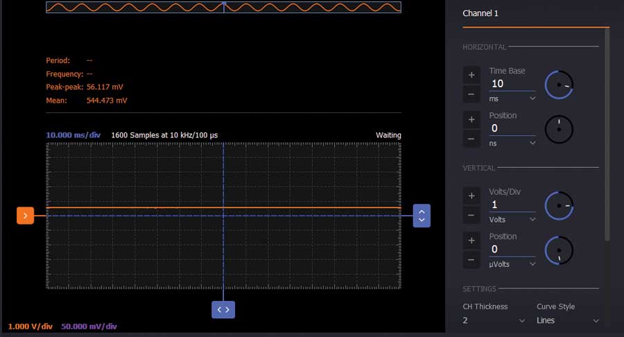
Select a resistor from the kit that is closest to the value computed for R4. Round up to make any error result in a higher output voltage. Place R4 in the circuit as shown in the schematic in Figure 6. Also, it is shown in Figure 8 how this resistor is placed on the breadboard. For this case, the closest value available in the kit is 200 kΩ. On Channel 1 of the oscilloscope you can see that the output offset voltage has dropped to the lower end of the linear range, close to the desired 0.5 V level.

Magnetic Proximity Sensor with LED Indicator
You can use an LED at the output of the proximity sensor as a visual indicator. The connection can be done as in Figure 8. Place a 100 Ω resistor between the anode of the LED and the output of the sensor. This will limit the current through the LED. The cathode is connected to GND. You will notice that the LED light intensity increases as the electromagnet is closer to the chip because the magnetic field increases the output voltage of the sensor.

Questions:
1. How will the response of the circuit change if the value of the inductor is changed?
2. Why do we want to lower the output offset voltage?
You can find the answers at the StudentZone blog.


