Sometimes You Need a Little Gain Part 1
Read other articles in this series.
Introduction
The LTC2373-18 is an 18-bit, 1Msps, 8-channel SAR ADC with an integrated high performance reference and programmable sequencer. The LTC2373-18 can be configured to accept both pseudo-differential (unipolar and bipolar) and fully differential input signals. For best performance, an op amp should be used to drive the MUX analog inputs. The LTC2373-18 datasheet shows several alternatives for buffering or attenuating the input signal. This article will explore applications where a gain of more than one may be required and will only deal with pseudo-differential drive. A future article will deal with fully differential drive.
The LT6236 is a goodop amp choice for this application because of its high bandwidth, low noise, low supply current and low offset. The LT6236 is a 215MHz gain bandwidth product, rail-to-rail output op amp/SAR ADC driver that features 1.1nV/√Hz input referred noise voltage density and draws only 3.5mA of supply current with a typical offset of only 100µV. The driver circuit presented here has been characterized over a range of gains and input frequencies in an attempt to give the potential user a good idea of the driver’s suitability for their application.
| Rg | Rf | Gain | AIN Range |
| ∞ |
24.9 | 1 | 0-4.096V |
| 499 | 499 | 2 | 0-2.048V |
| 499 | 2000 | 5 | 0-0.8192 |
| 499 | 4530 | 10 | 0-0.4096V |
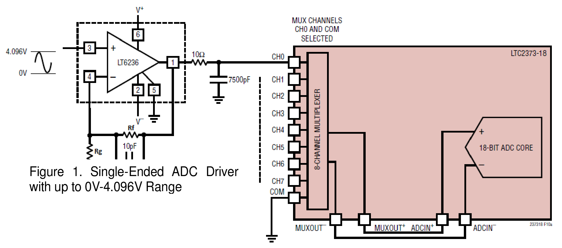
The circuit of Figure 1 is a non-inverting amplifier driving the LTC2373-18.The driver has a gain between one and ten depending on the values of Rg and Rf as shown in Table 1. The 10ohm, 7500pF lowpass filter on the output of the LT6236 limits the ADC MUX input bandwidth to 2.1MHz. The capacitor also acts as a charge reservoir for the ADC sample-and-hold capacitor and helps to isolate the LT6236 from the transient that occurs at the MUX input when the ADC goes into sample mode. The resistor is also used to help isolate the op amp from the ADC sampling transient.

Figure 1. Pseudo-Differential Driver for LTC2373-18 with Gain Range of 1 to 10.
Driver Performance
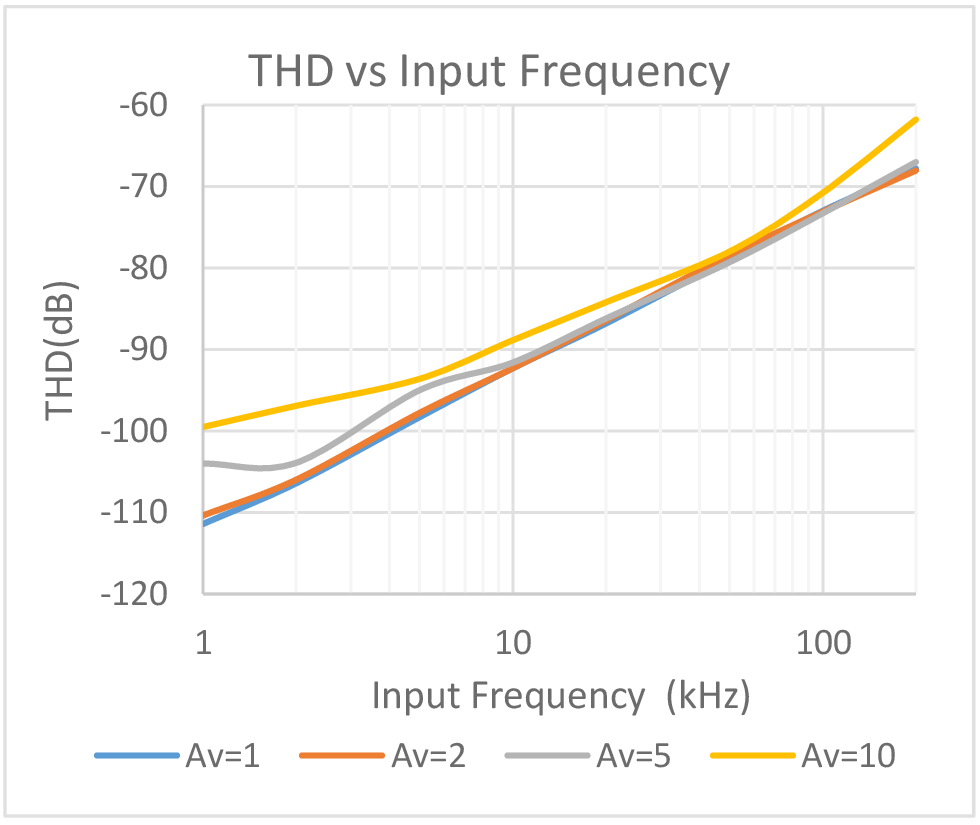
As shown in Figures 2 and 3, with a gain of 1 this circuit has an SNR of 95dB and a THD of -111dB with a sampling rate of 1Msps and a 1kHz input frequency. These numbers are close to the typical data sheet performance specifications for the LTC2373-18 by itself, indicating that the circuit performance in a gain of one is not degrading the ADC. Looking at Figure 2 which shows THD performance vs input frequency for gains of one through ten, it can be seen that the THD climbs above -90dB with input frequencies over 10kHz regardless of which gain is selected. By 150kHz THD has climbed above -70dB regardless of which gain is selected. This would suggest that the ADC is the limiting factor.

Figure 2. THD vs Input Frequency for the Circuit of Figure 1.

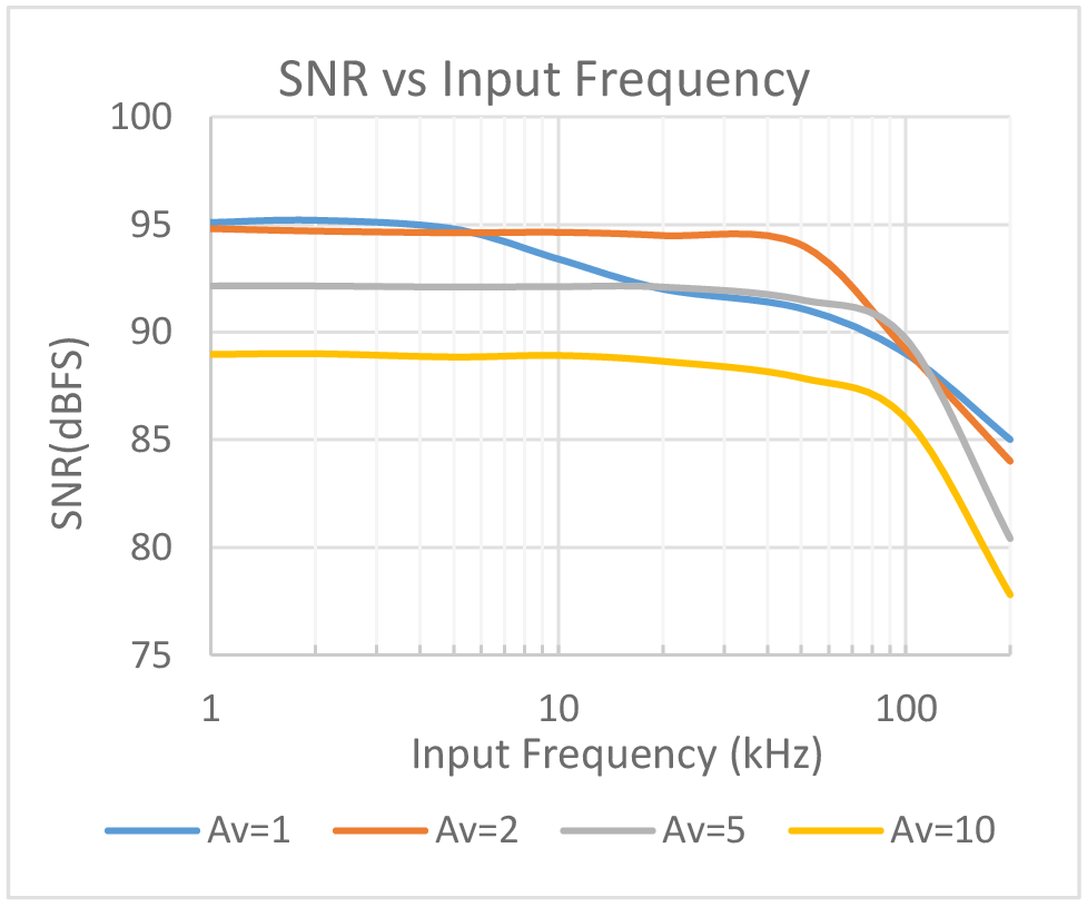
Figure 3. SNR vs Input Frequency for the Circuit of Figure 1.
Looking at Figure 3 which shows SNR performance vs input frequency for gains of one through ten, it can be seen that the SNR starts at 95dB for an input frequency of 1kHz and gains of one or two but falls off as the input frequency and gain rises. At a gain of one, SNR is reduced to 92dB beyond 50kHz. At a gain of two or five, SNR is reduced to 92dB at approximately 75kHz. At a gain of ten, SNR even at 1kHz is only 89dB and is reduced to 78dB by the time fin is increased to 200kHz. With a gain of one or two SNR performance is limited by the ADC. With gains of five or ten, the LT6236 limits the SNR performance.
关于作者
T他的职业生涯始于LTC,当时的职位是技术员,并向参与多个产品工作的Bob Dobkin、Bob Widlar、Carl Nelson和Tom Redfern学习,涉及产品包括运算放大器、比较器、开关稳压器和ADC。在此期间,他还花了大量时间来编写测试程序以对这些器件的特性进行表征。


