Single IC Monitors Redundant –48V Supplies and Fuses without Precision External Components
Single IC Monitors Redundant -48V Supplies and Fuses without Precision External Components
2003-12-01
Introduction
Reliability is a top priority for the designers of modern telephone and communications equipment. Designers take extra care to protect circuitry from failure by employing redundancy whenever possible, especially for power supplies. Supply voltages and fuses are monitored for early warnings of impending failure, often via a complicated array of precision components. The resulting circuits are expensive in terms of component cost, board space and engineering time. The LTC1921 replaces complicated monitoring systems with a simple, yet versatile, integrated precision monitoring system contained entirely in an MSOP−8 or SO−8 package.
LTC1921 is a high precision, all-in-one monitor for redundant −48V supplies. This device is the only fully integrated dual −48V supply monitor that meets common telecom specifications for supply range warning and can also withstand the high transient voltages required by telecom systems. Using a second LTC1921, dual −48V systems which have both −48V supply and return diodes and fuses on the same card can be monitored. The LTC1921-based circuits described in this article can be used to monitor a complete redundant 4-diode −48V supply system with guaranteed precision with just a few external components.
How it Works
The LTC1921 monitors supply voltages by dividing the voltage internally and comparing the result to an internal precision reference. No precision external components are required, thus ensuring maximum accuracy while simultaneously reducing component cost, board space and engineering requirements. The LTC1921 has telecom industry accepted preset voltage thresholds including undervoltage (−38.5V), undervoltage recovery (−43V) and overvoltage (−70V). The overvoltage threshold has a 1.3V hysteresis that defines the overvoltage recovery threshold. These thresholds are factory trimmed to meet the exacting requirements common to most power supply specifications. This eliminates the need to calculate the aggregate error of discrete components (i.e. the otherwise required separate reference, multiple comparator offsets, and resistors).
The LTC1921 is designed to indicate proper supply status over a wide range of conditions. In order to accomplish this, the internal architecture is symmetrical. The LTC1921 is powered via the supply monitor input pins, VA and VB. Supply current can be drawn from either or both pins, so the device can operate properly as long as at least one supply is within the operating range. Since power is not drawn from downstream of the ORing diodes, the LTC1921 functions properly even if the fuses or diodes are not functional.
Application Example
The LTC1921 measures two supply voltages by comparing them to a common reference. This requires that the returns be common, as is the case with many telecom switch cards. Some applications, however, have both supply and return OR diodes on the switch card. If an application requires separate monitoring of the returns, and possibly return fuses, a second LTC1921 can be used.
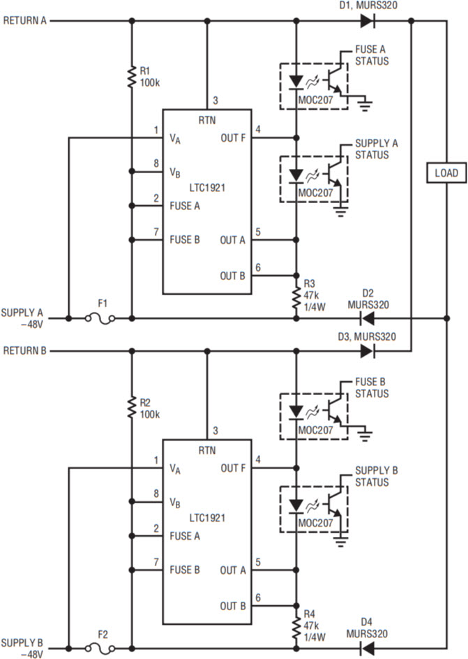
One of many possible configurations, Figure 1 shows a circuit that allows the monitoring of multiple returns. In this circuit each LTC1921 acts independently, with the RTN pins wired to the return pins at the card edge rather than the OR point which combines the returns. By monitoring the individual supply and return signals, the monitors are able to compare the supply voltages at the card edge without the diode drop of the return ORing diode. This circuit essentially duplicates the output circuitry, so that there are four outputs, each with a separate optoisolator. The outputs of the optoisolators may be combined in AND or OR fashion, but all four are required. In this circuit, if either supply voltage falls out of spec, its respective indicator changes to a warning state. If a fuse opens or the supply fails entirely, then all indicators for that supply indicate a warning.

Figure 1. An LTC1921 monitors each supply at the card edge in a 4-diode application.
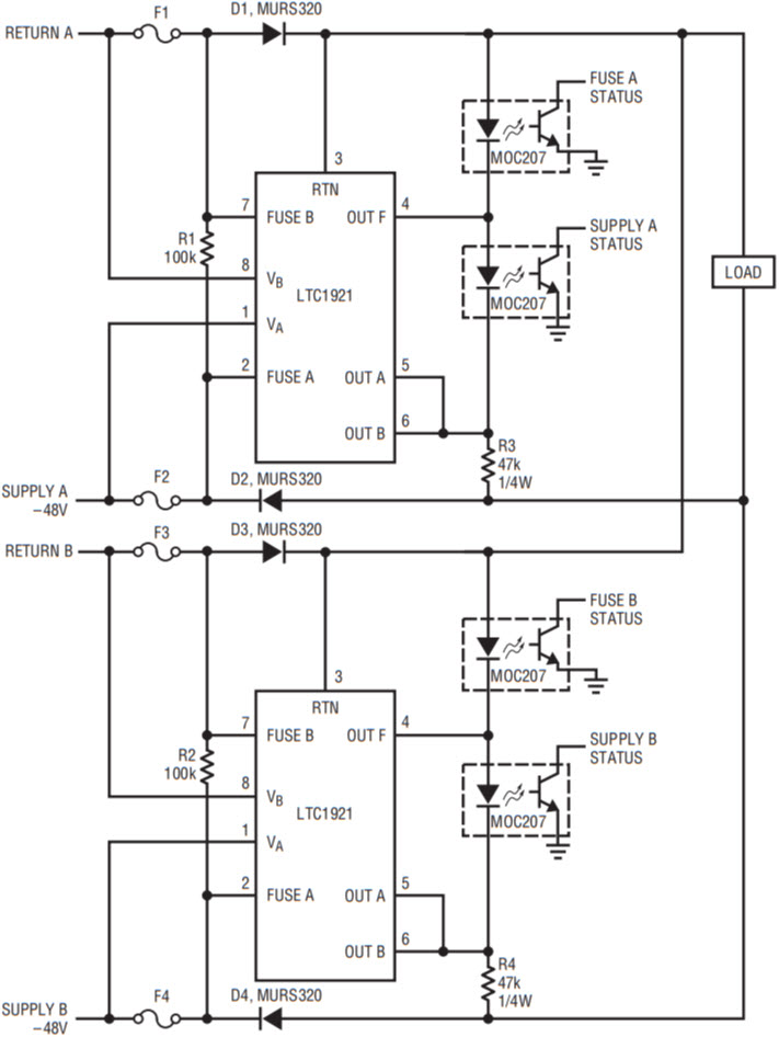
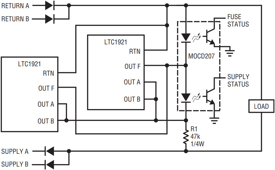
Figure 2 shows a slightly different approach. Each RTN pin in this case is wired to the combined return point. One LTC1921 is used for each supply. The circuit, while using essentially the same components as the previous example, provides added benefits. The outputs of the two LTC1921s can be wire-ORed directly, if required, reducing the number of optoisolators. If separate fuse or supply warnings are not required, then any or all of the outputs of the two monitors may be combined, as shown in Figure 3. In addition, the secondary supply/fuse monitor pairs (VB and FUSEB) can be used to monitor a return-line fuse or diode. This is possible due to the symmetrical nature of the LTC1921. Power can be drawn entirely from VA, while VB serves only as a reference for the return fuse monitor pin (FUSE B), illustrating the flexibility of this part.

Figure 2. Two LTC1921s monitor supply voltages, plus supply and return fuses for redundant −48V supplies.

Figure 3. Supply and fuse status outputs combined into one dual optoisolator.
Finally, the combined RTN reference allows each supply monitor to properly indicate status even if a fuse opens, since power is supplied to both sets of outputs as long as at least one supply is functional.
Conclusion
The LTC1921 reduces the board space, component costs and engineering time devoted to telecom power supply monitoring circuitry. It provides an integrated precision monitoring system contained entirely in an MSOP−8 or SO−8 package. Despite its remarkably simple setup requirements, the LTC1921 is flexible enough to work in a wide variety of complicated redundant power supply systems.
关于作者
Brendan Whelan is the Design Director for Switch, Mux, Reference and Temp Sense products at Analog Devices. He is responsible for DC precision products including voltage references and Silicon temperature sensors, as well ...


