New 5-Lead SOT-23 Oscillator is Small, Very Stable and Easy to Use
Introduction
Generating a periodic waveform of arbitrary frequency is not always a trivial task. Low cost RC oscillators can be built using discrete components such as comparators, resistors and capacitors, or by using simple integrated circuits such as the industry-standard 555 timer in conjunction with several discrete components. These solutions are bulky and inaccurate, especially at frequencies above a few hundred kilohertz.
Very accurate oscillators with a predetermined frequency may be realized using either crystals or ceramic resonators as stable frequency elements; crystal oscillators offer the highest performance, although they are costly. These circuits are also bulky, sensitive to acceleration forces and tend to be less robust than RC oscillators. Generating various frequencies from a single crystal or ceramic oscillator requires additional circuitry that will add to the component list and consume PC board space.
Enter the LTC1799
The LTC1799 offers an alternative that combines the frequency stability and accuracy of a ceramic resonator with the flexibility and ease of use of an RC oscillator, while requiring less space than either.
The LTC1799 is the only oscillator IC that can accurately generate a square wave signal at any frequency from 5kHz to 20MHz without the use of a crystal, ceramic element or existing clock reference. A complete oscillator circuit requires only an LTC1799, a frequency-setting resistor (RSET) and a bypass capacitor, as illustrated in Figure 1. With a 0.1% resistor, the frequency accuracy is typically better than ±0.6%. The LTC1799’s internal master oscillator is a resistance to frequency converter with an output range of 500kHz to 20MHz. A programmable on-chip frequency divider divides the frequency by 1, 10 or 100, extending the frequency range to greater than three decades (5kHz to 20MHz).
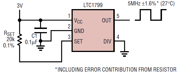
Figure 1. A complete oscillator solution.
Selecting the proper resistor is straightforward because the LTC1799 follows a simple relationship between RSET and frequency:

where N is the on-chip divider setting of 1, 10 or 100, depending on the state of the DIV pin. A proprietary feedback loop maintains this accurate relationship over all operating conditions, providing a temperature coefficient that is typically less than ±0.004%/°C. The LTC1799 operates over a 2.7V to 5.5V supply range, with a voltage coefficient of 0.05%/V. It typically draws 1mA of supply current. Figure 1 shows a circuit that generates a precision 5MHz signal.
LTC1799: Advantages in Precision, Resolution and Size
With a frequency tolerance 0.5% typical and 1.5% worst-case, the performance of the LTC1799 is similar to that of ceramic resonators and vastly superior to oscillators that use discrete resistors and capacitors. Its stingy temperature and voltage coefficients (typically ±0.004%/°C and 0.05%/V, respectively) maintain accuracy over all operating conditions.
Unlike oscillators using crystals, the LTC1799 has infinite frequency resolution; the output frequency can be set to any value in the 5kHz to 20MHz range. The programmed frequency is limited only by the choice of RSET. This feature allows the clock frequency to be changed late in a design cycle by changing the value of a resistor instead of stocking crystals in many different frequencies.
The LTC1799’s SOT-23 package and low component count (one resistor, one capacitor) result in an efficient use of PCB space, requiring less space than any crystal, ceramic resonator or discrete oscillator solution.
Frequency Set by Single Resistor and Ranged by an Internal Frequency Divider
The heart of the LTC1799 is a master oscillator that performs a precise resistance-to-frequency conversion. RSET can be any value from 3.32k to 1M, generating master oscillator frequencies between 30MHz and 1kHz with guaranteed 1.5% accuracy for resistors between 5k and 200k. To extend its frequency range, the LTC1799 includes a programmable frequency divider. The DIV input pin may be connected to GND to pass the master oscillator output directly to the OUT pin. When the DIV pin is left floating, the LTC1799 divides the master oscillator frequency by 10 before driving OUT. Connect DIV to V+ to divide the master oscillator by 100 to generate frequencies below 100kHz. Table 1 suggests the proper DIV pin setting for the desired frequency. The frequency ranges overlap near 100kHz and 1MHz, allowing a choice of settings. Since the supply current increases with smaller values of RSET, the lower divider setting is usually preferred.
| Divider Setting | DIV (Pin 4) Connection | Frequency Range |
| ÷1 | GND | > 500kHz* |
| ÷10 | Floating | 50kHz to 1MHz |
| ÷100 | V+ | ² 100kHz |
| *At frequencies above 10MHz (RSET <10k), the LTC1799 may suffer reduced accuracy on supplies less than 4V. | ||
Once the divider setting has been selected, calculate the proper resistor value using this simple equation:

Since the oscillator frequency, fOSC, is dependent on the resistor value, RSET, any error in the resistor will create error in fOSC.
Performance Rivals Ceramic Resonators
The LTC1799 obeys its frequency vs RSET equation within 1.5% at room temperature with any RSET from 10 to 200k for a frequency range of 5kHz to 10MHz. With a 5V supply, this range is extended to resistors as low as 5k, for frequencies up to 20MHz. Figure 2 shows the frequency deviation from the equation over the range of possible values for RSET. Figure 3 shows the output frequency variation over the industrial temperature range.
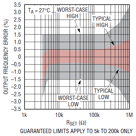
Figure 2. Accuracy of the output frequency equation.
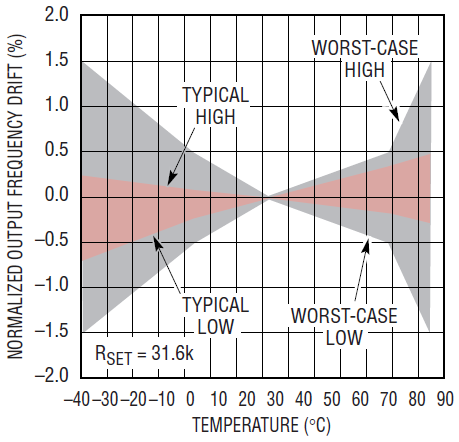
Figure 3. Output frequency temperature drift.
Applications
Temperature-to-Frequency Converter
In Figure 4, the frequency-setting resistor is replaced by a thermistor to create a temperature-to-frequency converter. The thermistor resistance is 100k at 25°C, 333k at 0°C and 16.3k at 70°C, a span that fits nicely in the LTC1799’s permitted range for RSET. With its low tempco and high linearity, the LTC1799 adds less than ±0.5°C of error to the output frequency. Figure 5 plots the typical and worst case output frequency vs temperature (error due to the thermistor is not shown).
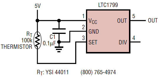
Figure 4. Temperature-to-frequency converter.
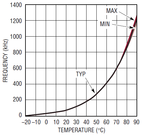
Figure 5. Output frequency vs temperature for Figure 4’s circuit.
80Hz to 8kHz Sine Wave Generator
Figure 6 shows the LTC1799 providing both the clock source and the input to a switched capacitor filter to generate a low distortion sine wave output. The 74HC4520 counter divides the frequency by 64 before driving the filter with a square wave. An ideal square wave will have only odd harmonics. The LTC1067-50 filter building block is configured as a lowpass filter with a stopband notch at the third harmonic of the desired sine-wave frequency. The fifth and higher-order harmonics are attenuated by 60dB or greater. The resulting sine wave has less than 0.1% distortion. This design can generate any tone from 78Hz (the LTC1799 minimum output frequency of 5kHz/64) to 8kHz, limited by maximum clocking frequency of the LTC1067-50 at a 3V supply. Figure 7 shows a scope capture for a 1kHz tone (RSET = 158kΩ).
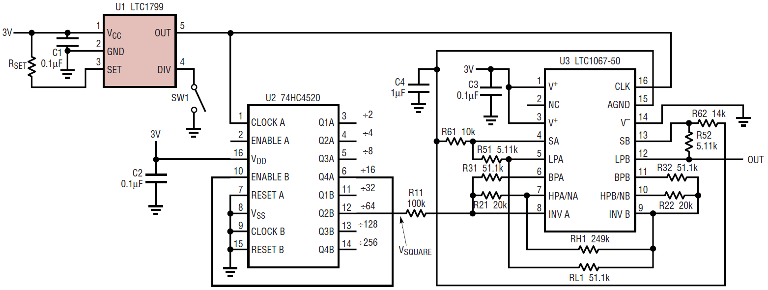
Figure 6. 80Hz to 8kHz sine wave generator.

Figure 7. Scope capture for a 100kHz tone (RSET = 158k).
Digital Frequency Control
Figure 8 shows the details of an LTC1799 controlled by a 12-bit voltage output D/A converter. Since the LTC1799 is a resistance-to-frequency converter, the input voltage between VCC and SET must be measured and used to create a current. Therefore, the DAC and op amps create a digitally controlled resistor between VCC and SET. Figure 9 shows the measured output frequency vs input code. The linearity is excellent except at the endpoints; the low frequency accuracy is limited by op amp offset and gain errors, while the highest frequency is limited by the op amp’s maximum output voltage.
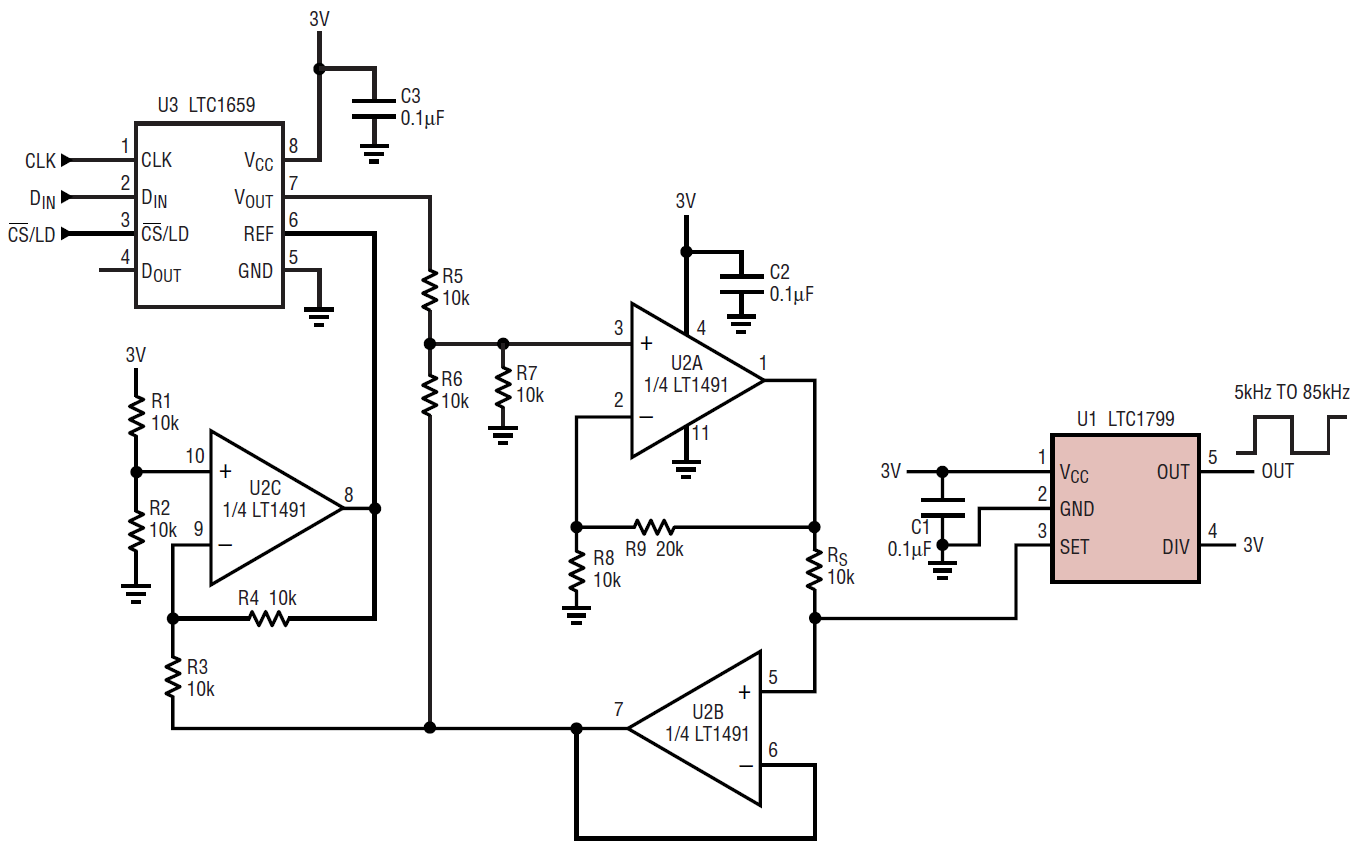
Figure 8. Digitally controlled oscillator with 5kHz to 85kHz range.
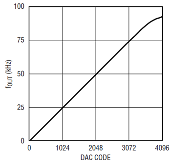
Figure 9. Input code vs output frequency for Figure 8’s circuit.
Conclusion
The LTC1799 is a tiny, accurate, easy-to-use oscillator that is programmed by a single resistor. With a typical frequency accuracy of better than 0.5% and low temperature and supply dependence, the LTC1799 provides performance that approaches that of crystal oscillators and ceramic resonators without sacrificing PCB space. Furthermore, the output frequency has unlimited resolution because it is resistor-programmable. With its resistance-to-frequency conversion architecture, the LTC1799 delivers an unprecedented combination of simplicity, stability, precision, frequency range and resolution in a tiny SOT-23 package.


