摘要
This tutorial explains how computed tomography (CT) imaging systems generate 3-D images of internal body structures. The high-end spiral CT technique is explained, as is the method by which light collected from photodiodes is processed into an electrical signal and eventually converted to a digital format by a digital acquisition system (DAS). This conversion process must happen quickly, which makes ADC sampling speeds and resolutions critical for CT designs.
Overview
Computed tomography (CT) medical-imaging systems generate three-dimensional (3-D) images of internal body structures using complex x-ray and computer-aided tomographic imaging techniques
The x-ray images used to generate the tomographic images are generated first by exposing the patient to a fan-shaped x-ray beam and then detecting the projected image on a thin semicircular, digital x-ray detector. The patient is placed between the source and detector, and the detector is configured with its geometric center located at the x-ray source. Each image is an x-ray projection of a very thin transverse slice of the body. To collect the multitude of x-ray projections necessary to generate a tomographic CT image, both the x-ray source and detector are rotated about a patient within a supporting gantry. While the source and detector rotate, images are collected and stored. As in a traditional x-ray, the signal levels in the image slice represent the relative radio density of the patient along a line from the x-ray source to the corresponding pixel location.
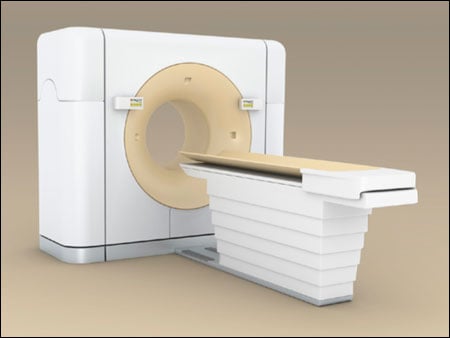
To improve image-capture times and resolution, manufacturers utilize multislice CT imaging techniques. Instead of a single 2D detector array which provides only a single image slice, multislice imaging uses a 3-D array. The added imaging dimension allows the system to generate multiple slices in parallel. Photodetector arrays used in CT imaging have as many as 1000 detectors in the long dimension along the semicircular detector arch; 16 or more detectors are positioned in the shorter dimension tangential to the arch. The number of detectors in the short dimension determines the number of available image slices.
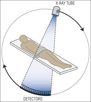
The patient is exposed to a fan-shaped x-ray beam and the projected image is detected on a thin, semi-circular digital x-ray detector.
Modern CT imaging systems can also generate images in any plane within the body by using a technique called spiral CT. In a spiral-CT system the patient is slowly moved into the center of the gantry while the x-ray source and detector rotate about the patient. Very-high-speed computers are necessary to process the images collected in this manner. Sophisticated tomographic imaging techniques are used to produce the required image.
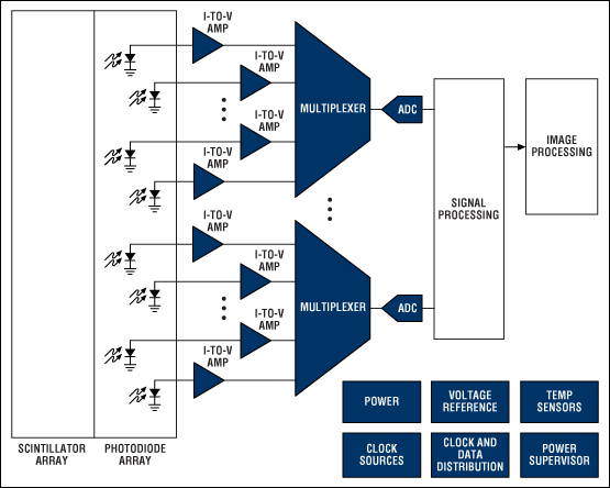
Block diagram of a CT imaging system. For a list of Analog's recommended CT imaging solutions, please go to: www.analog.com/ct-imaging.
X-Ray Detection
Early CT imaging systems accomplished x-ray detection using both scintillation crystals and photo-multiplier tubes. The scintillation crystals converted x-rays to light and the photomultiplier tubes converted these light signals to a usable electrical signal. Modern CT systems now employ more sophisticated scintillation crystal materials and solid-state photodetector diodes for this purpose.
The output from each photodiode is a current proportional to the light striking the diode. These currents can be directly converted to a voltage by a low-noise transimpedance amplifier (TIA), or integrated over time using a capacitor or active integrator op-amp circuit to produce a voltage output. Integration of the current from each diode can be accomplished in multiple ways. Capacitance in the photodiode detector array itself can be used for this purpose. The signals from these capacitors are multiplexed using FET switches in the diode-array detector. The signals are then routed to the digital acquisition system (DAS) which amplifies and converts the signals to a digital format using high-resolution analog-to-digital converters (ADCs). An alternative method routes the signals from every photodiode to an integrator in the DAS. In these implementations, the integrated current signals are converted to a voltage, sampled at the same time, and multiplexed into the input of an ADC.
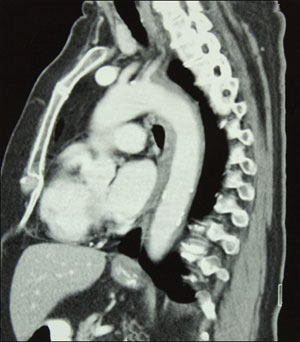
The time required to capture a single x-ray image varies widely, but can be as short as 100µs. The sampling speed of the ADCs used in the DAS to convert these signals largely determines the amount of multiplexing and, hence, the number of converters and amplifiers in the system. The ADCs' dynamic range must be large to preserve the large dynamic range of the x-ray image. Converters with 16-bit resolution or greater are common. The outputs of the ADCs are routed to an image signal processor over a high-speed bus for further signal processing and image reconstruction. In some implementations, the digital processing can be physically separated from the ADCs by a reasonable distance. In these cases, high-speed line drivers are used to route the signals.
Tomographic Imaging
The resulting x-ray image data set is converted to an image by the image processor. The image processor is typically a very-high-speed computer which performs the massive calculations required for the tomographic image reconstruction. The resulting image will commonly have a very large dynamic range (i.e., 16-bit grayscale images). Further image processing is necessary to map this large dynamic range most effectively into the limited visible display range.


