High Efficiency, Monolithic Synchronous Buck-Boost LED Driver Drives up to 1A Continuous Current
High Efficiency, Monolithic Synchronous Buck-Boost LED Driver Drives up to 1A Continuous Current
by
Aspi Gazder
2005-12-01
Introduction
The LTC3454 is a synchronous buck-boost DC/DC converter, designed for driving a single high power LED with regulated currents up to 1A from a single Li-Ion battery. Switching converters are typically used to regulate a voltage, but LEDs require constant current to generate predictable light output. The LTC3454 uses an autozero transconductance error amplifier in its regulation loop to accurately control LED current. The LED current can be set to one of four levels, including shutdown, using two external resistors and dual enable pins. In shutdown no current is drawn.
The wide VIN range of a Lithium-Ion battery (2.7V to 4.2V) requires that a converter be able to both step-up and step-down the input voltage when the LED forward voltage is within the range of the battery discharge profile. The LTC3454 LED driver efficiently performs step-up and step-down conversion via four internal switches. The regulator operates in synchronous buck, synchronous boost or buck-boost mode, depending on VIN and the LED forward voltage. Transitions between modes are automatic and smooth.
The LTC3454 operates at a high fixed frequency of 1MHz, which reduces inductor size and eases output filtering.
Application
Figure 1 shows the LTC3454 driving a high power LED in torch and flash modes. Only six external components are required in this application. Efficiency, PLED/PIN, greater than 90% is possible over the entire usable range of a Li-Ion battery (see Figure 2).
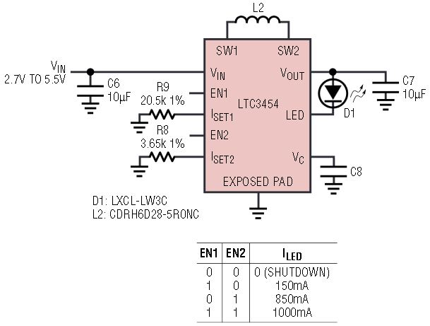
Figure 1. LTC3454 used in a typical application.
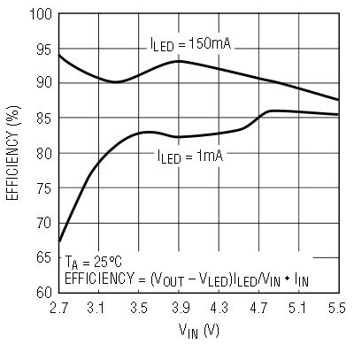
Figure 2. Efficiency for circuit of Figure 1.
The LTC3454 has two enable pins that control two current setting amplifiers. A resistor connected from an ISET pin to GND programs the LED current to:

when the current setting amplifier is enabled via its EN pin. When both enable pins are asserted, the net LED current is the sum of each individually programmed current. Figure 3 shows schematically how the LED current is programmed.
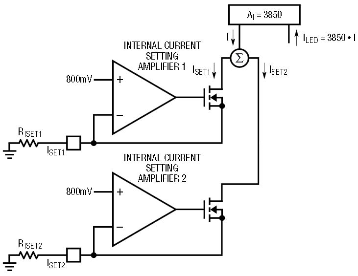
Figure 3. Two current setting amplifiers give the user the flexibility to choose more than one non-zero current level.
Autozeroing Transconductance-Amplifier-Based Current Regulation
The LTC3454 employs an auto-zeroing transconductance amplifier in its regulation loop, as shown in Figure 4. The autozero amplifier topology nullifies any offset at its input, allowing an accurate LED current to be achieved with very low common mode input voltage levels, resulting in high PLED/PIN efficiency. The regulation voltage present at the LED pin can be as low as 100mV at 100mA of LED current.
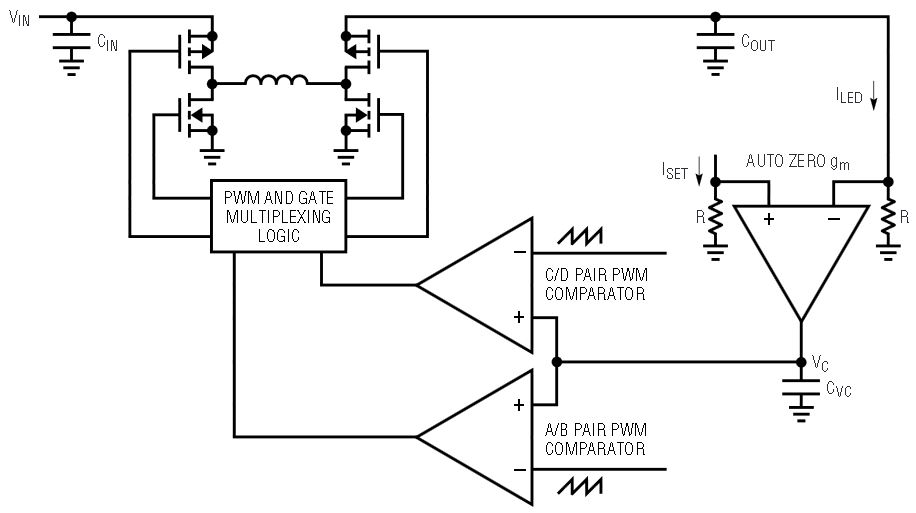
Figure 4. An auto-zeroing transconductance amplifier maintains loop regulation.
Synchronous Buck-Boost DC/DC Converter
The LTC3454 can drive an LED at up to 1A continuous current. LEDs that can be driven with such high current typically have forward voltage drops of 3.3V – 3.6V. When powered from a single Li-Ion battery (2.7V to 4.2V), as in the case of handheld battery powered applications, neither a pure buck nor a pure boost solution can efficiently regulate the LED current. A pure buck would dropout at lower battery voltages, causing a lower than programmed LED current to flow. At high battery voltages, a pure boost converter would regulate a higher output voltage than necessary, resulting in low efficiency. The buck-boost converter can efficiently regulate LED current over the entire Li-Ion battery range.
The control voltage, VC, determines the region of operation of the buck-boost converter. The gate drives of the internal power switches A, B, C and D are controlled by the logic block (Figure 4). A patented gate drive multiplexing scheme enables smooth transition between buck and boost modes and through the four-switch region. In buck mode, the duty cycles on gate drives of switches A and B are controlled while switch D is turned on continuously. In boost mode, duty cycles of switches C and D are controlled, while switch A is on continuously.
Using synchronous rectifier switches B and D instead of catch diodes helps improve efficiency. This scheme requires that the synchronous rectifier switch and the main switch are not turned on simultaneously. A cross conduction delay prevents this condition from occurring. The LTC3454 has a break before make time of approximately 30ns. During this time the current conduction path is completed through the body diodes of the switches. In the case of forward current flow from the SW1 pin to the SW2 pin through the inductor, the body diode of NMOS switch B conducts in buck mode. The SW1 node is pulled a diode drop below ground. Likewise, in boost mode, the body diode of PMOS switch D conducts during the switch C and switch D switching, but node SW2 now flys above VOUT by a diode drop. Body diodes of the main switches A and C conduct during reverse current flow. Figure 5 shows the switch waveforms in the buck-boost mode.
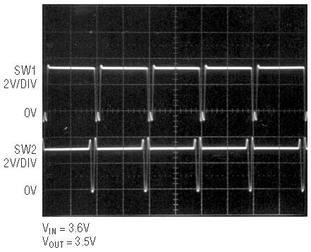
Figure 5. Switching waveforms in buck-boost mode.
The LTC3454 has both forward and reverse current limiting—requiring no external sense resistors. If the peak input current exceeds approximately 3.4A, forward current limit is tripped and switches B and D are turned on for the rest of the cycle. The reverse current limit is tripped when current flowing from switch D through the inductor to the SW1 node exceeds approximately 250mA and switches A and C are turned on for the rest of the cycle.
Robust Design:
Can Tolerate Open and Shorted LED Conditions
If the LED faults as an open circuit, the regulation loop drives VC higher, which has the effect of raising the output voltage. A safety amplifier—a transconductance amplifier with sink only capability—takes control of the regulation loop and prevents VOUT runaway. The VOUT threshold at which this happens is approximately 5V.
If the LED faults as a short circuit, the regulation loop continues to regulate the output current to its programmed current level.
Conclusion
The LTC3454 adds to Linear Technology’s family of LED drivers. High efficiencies can be achieved over the entire Li-Ion range with a minimal number of external components. Additionally, it draws zero current when in shutdown, helping conserve battery life in hand held battery powered applications. The LTC3454 is available in a low profile small footprint 3mm × 3mm DFN package.


