摘要
One of the vulnerabilities of Global Navigation Satellite Systems (GNSS) is the receiver’s inability to get a \"good read\" from a compromised satellite signal. This uncertainty is usually due to a lack of a direct line-of-sight. This application note identifies the constellations that rotate around the earth, then proceeds to a discussion of the GNSS receiver’s interference sources. This thorough constellation and error source examination concludes with a description of receiver architecture that significantly reduces direct line-of-sight errors by accepting multi-band and multi-constellation signals.
Concerned About GNSS Inaccuracy? Expand Your Constellations
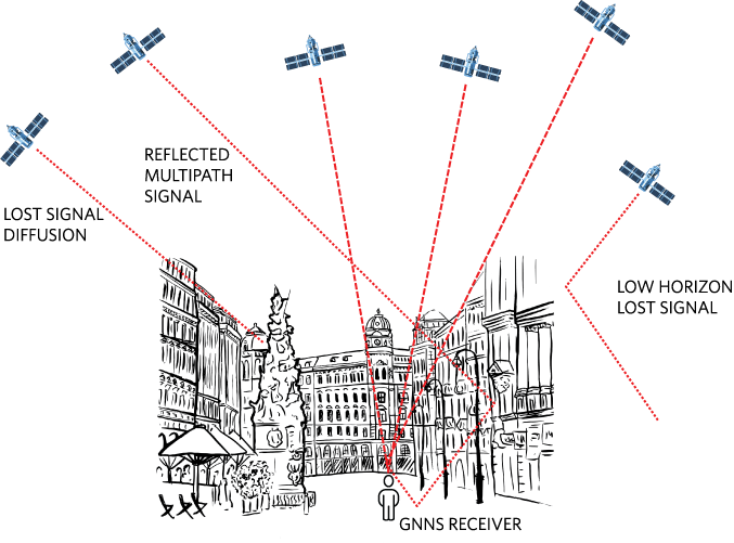
One of the weaknesses of Global Navigation Satellite Systems (GNSS) is the inability of receivers to determine their accurate position from compromised satellite signals. This uncertainty may be due to a lack of a direct line-of-sight between the satellite and receiver. Or the satellite may be low on the horizon, increasing the risk of multipath errors and of signal attenuation due to propagation through the atmosphere. This reception problem is prevalent around the world, but particularly in the big city’s urban canyons (Figure 1).

Figure 1. Unable to See Your Way Out of the City? So do GNSS Signals!
An unsatisfactory workaround is to depend on WiFi or a local area internet. Several alternatives come close to solving this reception problem, but the most promising solution is to go back to the GNSS sources.
This design solution starts by providing a summary of GNSS satellite constellations. With the constellations identified, we proceed to a discussion of the GNSS receiver’s interference sources. This thorough constellation and error source examination concludes with a receiver architecture strategy that accepts multi-band and multi-constellation signals.
Multiple Constellations
GNSS contains multiple regional and global satellite constellations, all of which orbit around the earth. A single global constellation provides the desired coverage with a grouping of 20 to 30 satellites.

Figure 2. Various Constellations Orbit the Earth and are in Constant Contact with Receivers and Stations on its Surface.
At present, the six satellite constellations are:
GPS – The first GNSS system was GPS (Global Positioning System). The United States Department of Defense launched GPS in the late 1970s. With global coverage, GPS uses 31 constellation satellites with civilian frequency bands of L1 (1575.42MHz), L2 (1227.360MHz) and L5 (1176.45MHz).
GLONASS – The Russian Global Navigation Satellite System constellation has 24 satellites, with frequency bands L1 (1598.0625MHz to 1609.3125MHz) and L2 (1242.9375MHz to 1251.9375MHz). This constellation provides global coverage.
BeiDou – The Chinese BeiDou Navigation Satellite System (BDS) is a regional service that became operational in December 2012. This constellation will have 35 satellites by 2020, with frequency bands of B1 (1561.098MHz), B2 (1207.140MHz) and B3 (1268.520MHz). BeiDou will provide global coverage.
Galileo – Galileo is the European Union constellation and will ultimately have 27 satellites, with frequency bands E1 (1575.42MHz), E5a (1176.45MHz, E5b (1207.14MHz, and E6 (1278.75MHz). The schedule for full global coverage is 2020.
IRNSS – The Indian Regional Navigation Satellite System constellation has 7 satellites, with frequency bands of L5 (1176.45MHz) and S (2492.028MHz). The Indian Regional Navigation Satellite System (IRNSS) provides regional service to India and surrounding areas.
QZSS – The Japanese Quasi-Zenith Satellite System constellation has 4 satellites providing regional service to Japan.
GPS Error Sources
The determination of the fundamental performance of a GPS receiver hinges on error management. Lower errors provide a higher degree of positioning accuracy and reliability. Receiver designers have a direct influence on the overall error management. Table 1 quantifies the GPS L1 C/A signal errors.
| Contributing Source | Error Range | |||||
| Satellite Clocks | ±2m | |||||
| Orbit Errors | ±2.5m | |||||
| Ionoshperic Delays | ±5m | |||||
| Tropospheric Delays | ±0.5m | |||||
| Signal Arrival | ±3m | |||||
| Receiver Noise | ±0.3m | |||||
| Multipath | ±1m | |||||
| Note: The root-sum-square of these errors is equal to ±6.7m(rms). | ||||||
Satellite Clocks
GPS satellites have very accurate atomic clocks. This level of accuracy is good news, but the not-so-good news is the small amount of atomic clock drift. Even a small inaccuracy in a satellite’s clock produces a significant calculated receiver position error. As an example, a 10ns satellite clock error can produce 3m range error on the earth's surface.
The clock accuracies of the ground control systems around the world are better than the individual satellites. These ground control systems monitor the clock drift of the atomic clock of each satellite and upload satellite clock correction terms, which are then transmitted by the satellite down to Earth. A receiver then applies the satellite clock correction which results in a typical residual range error of ±2 meters.
Orbit Errors
Satellites follow elliptical orbits around the Earth which are determined mostly by the Earth’s gravity, but some of the concerns over potential errors are due to the following factors:
- “Third body” gravitational effect from the Moon and Sun
- Solar radiation pressure
- Earth’s non-uniform density
All these perturbations need to be accurately modeled to have sufficient accuracy in the estimate of the satellite’s position.
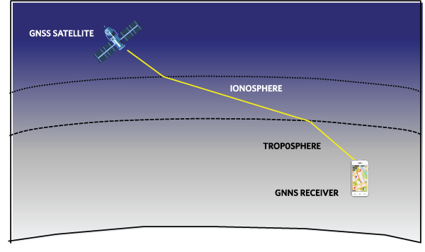
Ionospheric Delay
The ionosphere layer is between 50km and 1000km above the Earth’s surface. This layer contains electrically charged ions. These ions cause a significant amount of delay, which is timevarying (Figure 3).

Figure 3. Ionosphere and Troposphere Atmospheric Delays Occur Between the GNSS Satellite and GNSS Receiver.
The ionospheric delay varies with the GNSS radio frequency in a predictable way. By comparing the pseudo-ranges computed to a particular satellite using signals transmitted on two different carrier frequencies, a receiver can accurately estimate andcompensate for the ionospheric delay.
Tropospheric Delay
The closest atmospheric layer to the Earth is the troposphere. A change in humidity, temperature, or atmospheric pressure causes variations in the troposphere delay. Accurate models of the troposphere allow compensation for most of the tropospheric delay.
Signal Arrival Time
A GPS receiver estimates the arrival time of a satellite signal by comparing the received satellite’s spreading code sequence with a local replica. The achievable measurement resolution is typically 1% of one chip time of the code, corresponding to a 3m range error.
Multipath
Multipath signals occur with the reflection of a GNSS signal. These signals reflect off objects, such as the wall of a building or diffused by vegetation (Figure 4).

Figure 4. The City’s Urban Canyons Create Multipath Delays and Cause Lost Signal.
Reflected signals travel farther than the original signal to reach the receiver antenna. Consequently, the reflected signal arrives slightly later than the line-of-sight signal. It is possible that the delayed signal can cause a receiver’s miscalculation.
Bringing Multiple Constellations into View
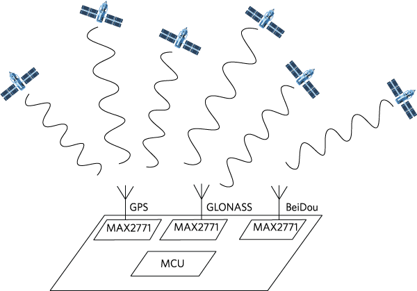
A multi-constellation receiver (Figure 5) accesses signals from several constellations. An increase in the number of satellites is an added benefit when using multiple constellations.

Figure 5. Multi-Constellation Receivers Allow the Reception of Multiple Frequency Bands.
Advantages of a multi-constellation receiver include:
- Reduction in acquisition time
- Improvement in position and time accuracy
- Reduction in building and foliage obstruction problems (multipath errors)
An effective way of overcoming interference is to acquire the signal from another constellation. Redundancy is built into the solution when receivers utilize signals from a variety of constellations.
Bringing the Signals Home
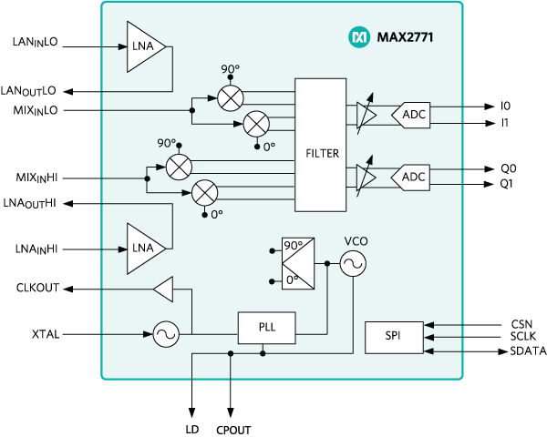
As shown in Figure 5, a multi-constellation GNSS receiver requires multiple receiver devices to capture the various frequency band signals. A complete front-end receiver chain has a dual-input LNA and mixer, followed by a filter, PGA, and multi-bit ADC, along with a fractional-N frequency synthesizer and crystal oscillator (Figure 6).

Figure 6. Multiband Universal GNSS Receiver.
The device in Figure 6 has programmable IF filter bandwidths and a high or low LNA, making it capable of receiving signals rom GPS, Galileo, GLONASS, BeiDou, IRNSS, and QZSS constellations. It supports all the frequency bands of the respective constellations with a fractional-N synthesizer and integrated crystal oscillator.
Conclusion
Many elements ensure there is a “good read” of the GNSS incoming satellite signals. GNSS receivers must accept and adequately condition the satellite’s small analog signal into a useful digital output. This design solution describes an integrated receiver front-end solution that receives signals from six satellite navigation constellations. This type of solution allows multiple constellations to provide an accurate, reliable, and quick estimate of the receiver’s location, velocity, and time making GNSS a more powerful satellite navigation system.


