摘要
Providing predictable and error-free communications, CAN bus networks have been the workhorse of the automobile industry for over thirty years. However, they have recently found a new lease on life in other industrial applications, including drones. In this design solution, we show where and how CAN transceivers can be used in drone designs and explain why it is important that they come with the high levels of electrical protection when used in this application.
Introduction
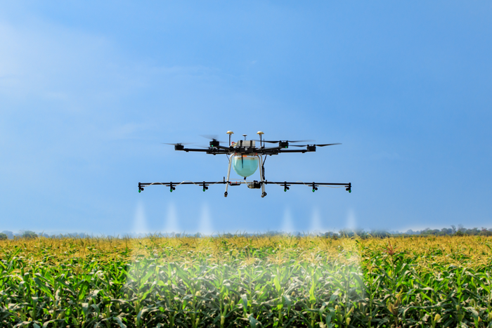
As the saying goes, “If it ain’t broke, don’t fix it.” Although it may not be new and exciting, it is perhaps the very simplicity and dependability of the controller area network (CAN) interface that has allowed it to not only survive, but continue to thrive in the technology jungle that the automobile industry has become. In a market where functionality and reliability are key, drivers of luxury models (which can incorporate up to 150 electronic control units) are most likely unaware (or don’t care) that the interface that allows these controllers to talk to each other is now over thirty years old. It is perhaps unsurprising that designers of other motorized products, including industrial drones (Figure 1), are now seeking to exploit some of the benefits that this “journeyman” of the interface world, can bring to their products.

Figure 1. A drone being used to spray crops.
With market forecasts for 2020 estimated at $900M, and many applications ranging from military to crop inspections, and from aerial photography to law enforcement, it is hard to imagine what drones will be used for in the future. In this design solution, we consider the basics of drone design and discuss both the opportunities and challenges this presents for CAN transceivers. We then present a CAN transceiver IC best placed to meet some of the distinct requirements of this burgeoning technology.
Basics of Drone Design
The fundamental electronics in a drone design include:
- Navigation
- Global Positioning System (GPS)
- Maneuverability
- Motor control
- Propellers
- Camera
- Gimbal function
- Autonomous operation
- Auto-stabilization
Two banks of highly efficient brushless DC (BLDC) motors communicate with the main controller, which impacts the drone’s location and camera position. In the background, the onboard sensors, such as global positioning system (GPS), the accelerometer and gyroscope, provide the direction information to the drone’s controller. The propeller and camera stability motors require a reliable communication physical backbone with a robust protocol. CAN is an excellent candidate for this function.
Motor Control Board
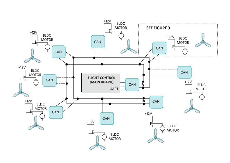
The propeller motor control electronics include the physical layer of serial communication devices, BLDC motors, and their drivers. Here, a CAN bus can be used to provide real-time control, high-level error handling, in addition to multi-master/multi-slave communications. The flight control circuit (Figure 2) is the heart of the drone system. Although each motor works independently, it must also operate in concert with the others.

Figure 2. The drone’s flight control board sends messages from four to eight propeller motors.
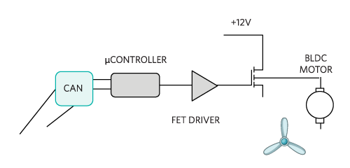
A CAN bus is ideal to allow the main control board to communicate with the controller responsible for each individual motor (Figure 3).

Figure 3. A detailed block diagram of the drone’s motor.
The BLDC motors have permanent magnets mounted on the rotor hubs and inductor windings on the stator arms. These motors use the concept of attraction or repulsion between magnetic poles. The motor movement starts when a current flow in the inductor windings generates a magnetic pole, attracting the closest permanent rotor magnet of the opposite magnetic charge. The rotor, which has a shaft connected to the hub, moves while the current switches to an adjacent coil. This sequence of charging each winding requires the rotor to continually follow. The flight control system manages messages from sensors and the pre-programmed flight plan, or from the user on the ground, and adjusts individual motor speeds appropriately.
Gimbal Function
The drone gimbal has its own bank of motors, which keep the camera in the same position with respect to the horizon. The gimbal pivots the camera mounts that rotate about the x, y, and z axes. This provides stabilization and the pointing of cameras or other sensors. Reliable communication between the gimbal and the main controller board can also be enabled by using a CAN bus interface.
Drone Protection
The CAN’s inherent single-bus arbitration protocol feature and reliable error checking are some of the main reasons to use it in industrial drones employed in critical applications like broadcasting, agricultural pesticide dispensing, and delivery of goods to residential or commercial buildings. However, when selecting a CAN transceiver, there are other some additional features to look for. Firstly, the IC must make the CAN bus as robust as possible. With many powerful motors operating simultaneously, power surges are common in drone circuits, especially at times when maximum uplift is needed quickly. These surges could potentially couple on to CAN bus, altering its common-mode voltage and interrupting communication between the main board controller and one (or more) motor controllers. For an aerial drone, even a temporary interruption to data communication between controllers could have catastrophic consequences. To protect against this, it is important to choose a CAN transceiver IC with the highest possible common-mode input voltage range (CMR). Secondly, to prevent damage during manufacture (e.g. due to manual handling or through accidental contact with other electrical equipment), high levels of ESD and battery short-circuit protection are also necessary features. A small form factor (to reduce board space) and low operating voltage (to extend battery life) are also important.
Small But Robust
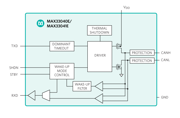
The MAX33040E (Figure 4) is a 3.3V, 5Mbps CAN transceiver, which is fully compliant with the CAN standard. An important benefit of this IC is that it provides ±25V extended CMR, which exceeds the ISO 11898-2 CAN standard (-2V to +7V). This ensures continued reliable communication with the drone’s motors during power surges. It also provides ±40kV of ESD HBM protection to protect the IC against potential damage during drone assembly. This transceiver also confers the benefit of extended ±40V fault protection, making it suitable for use in equipment where overvoltage protection is required and also to prevent damage in the event of a short circuit.

Figure 4. The MAX33040E 3.3V, 5Mbps CAN transceiver fully complies with the CAN standard.
This transceiver is available in an 8-pin SOIC package. However, for space-constrained applications, it can also be sourced in an 8-pin SOT23, which has the benefit of being 40% smaller and enables the most robust CAN bus implementation available in this package size.
Summary
Providing predictable and error-free communications, CAN bus networks have been the workhorse of the automobile industry for over thirty years. However, they have recently found a new lease on life in other industrial applications, including drones. In this design solution, we have shown where and how CAN transceivers can be used in drone designs and explained why it is important that they come with the high levels of electrical protection when used in this application. Finally, we presented a low-voltage, small footprint IC to make the CAN bus of an industrial drone as robust as possible. Apart from drone applications, this CAN transceiver IC is also suitable for use in other industrial equipment as well as instrumentation and building automation systems.


