400MHz Current Feedback Amps Offer High Slew Rate without the Gain Bandwidth Product Limitations of Voltage Feedback Amps
400MHz Current Feedback Amps Offer High Slew Rate without the Gain Bandwidth Product Limitations of Voltage Feedback Amps
2000-02-01
Introduction
The LT1395, LT1396 and LT1397 are 400MHz current feedback amplifiers with a high slew rate and a –3dB bandwidth that remains relatively constant over a wide range of closed-loop gains. The current feedback topology of the LT1395/LT1396/LT1397 family can provide improved performance in many new and existing designs that have historically used voltage feedback op amps. Because of its current feedback topology, the LT1395/LT1396/LT1397 family boasts a slew rate of 800V/µs on a supply current of only 4.6mA per amplifier, resulting in a much higher full-power bandwidth than comparable voltage feedback op amps. The current feedback topology of the LT1395/LT1396/LT1397 also results in additional design flexibility because the –3dB bandwidth remains relatively constant regardless of closed-loop gain. In contrast, the –3dB bandwidth of voltage feedback op amps decreases in proportion to the closed-loop gain that has been chosen. For example, a voltage feedback op amp with a 400MHz gain bandwidth product (GBW) will only have a 100MHz bandwidth at a closed-loop gain of four. At the same gain, the LT1395/LT1396/LT1397 have a gain bandwidth of about 240MHz. The parts have industry-standard single, dual and quad pinouts, allowing easy upgrades of existing applications.
The LT1395/LT1396/LT1397 Family
In addition to a 400MHz –3dB bandwidth and an 800V/µs slew rate, the LT1395/LT1396/LT1397 family has exceptionally flat frequency response. Applications that require gain accuracy across a broad frequency range will benefit from the family’s ±0.1dB bandwidth, which exceeds 100MHz. For increased design flexibility, the LT1395/LT1396/LT1397 also boast a very flexible output stage. They have over 80mA of output current drive and, on ±5V supplies, they can swing up to ±3.6V with a 150Ω load.
The LT1395/LT1396/LT1397 family’s wide supply voltage range and versatile packaging options also increase design flexibility. Supplies can range from a single 4V to ±6V. All devices and package types are compatible with standard op amp pinouts. In addition to standard SO packages, the LT1396 and LT1397 are also available in smaller form factors. The LT1396 is available in an 8-lead MSOP package. The LT1397 is available in a 16-lead SSOP package that takes the same amount of board space as an SO-8. The LT1395 will be available in SOT-23 soon.
A simplified schematic of a single amplifier from the LT1395/LT1396/LT1397 family can be seen in Figure 1. Transistors Q1–Q7, J1 and R1 generate the necessary internal bias currents, with Q6 and Q7 acting as current sources for the input stage. Transistors Q8–Q11 form the amplifier’s input stage. Currents coming from Q10 and Q11 are mirrored on top and bottom by transistors Q12–Q17. The collectors of transistors Q13 and Q15 drive the high impedance node of the amplifier. Transistors Q16 and Q17 act as current sources for the output stage. Transistors Q18–Q21 and resistors R2 and R3 form the output stage.
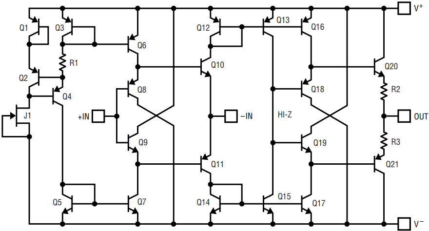
Figure 1. LT1395/LT1396/LT1397 simplified schematic (one amplifier).
It’s the Input Stage
The advantages of a current feedback amplifier (CFA) can be better understood by examining the internal circuit topology in greater detail. The LT1395/LT1396/LT1397 input stage reveals that the noninverting input drives the bases of Q8 and Q9, resulting in a high impedance input. On the other hand, the inverting input drives the emitters of Q10 and Q11 and results in a low impedance input; any differential voltage imposed across the inputs creates a current that flows into or out of the inverting input. This current modulates the collector currents of Q10 and Q11, is mirrored on top and on the bottom, and produces a voltage swing at the high-impedance node (and output) of the amplifier. Since the output voltage swing is based upon the current flowing through the inverting input, the gain of a current feedback amplifier is expressed as the ratio of output voltage change (dV) divided by inverting input current change (dIB–) and is referred to as the amplifier’s transimpedance (Z0).
A conventional voltage feedback input stage (Figure 2) is dramatically different than the current feedback input stage described above. The inverting input of the voltage feedback input stage is a high impedance input; thus, any feedback to this node is in the form of a voltage. Since the currents flowing into or out of the inverting input are small, the maximum slew current at the high-impedance node is derived from internal currents only and has an upper limit equal to the collector current of Q3. In contrast, the slew current in a CFA is not limited to internal currents; it is provided externally via the inverting input and results in much higher slew rates than those of conventional voltage feedback op amps.
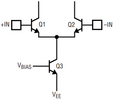
Figure 2. Voltage feedback input stage.
A CFA’s constant bandwidth over closed-loop gain can be easily explained if we derive equations for closed-loop gain and closed-loop bandwidth; we can then compare them with the equations for a voltage feedback op amp. Let’s start by comparing open-loop transfer functions and open-loop gain:
A conventional voltage feedback op amp has an open-loop gain AJF that defines the transfer function of the amplifier as follows:

where d(VIN) is the difference voltage between the noninverting input and the inverting input. Over frequency, AJF has a value at DC (A0) and a dominant pole frequency (fa). The open-loop response can be expressed as:

A current feedback amplifier has an open-loop transimpedance ZJF that defines the transfer function of the amplifier as follows:

where IB– is the current flowing out of the inverting input. Over frequency, ZJF has a value at DC (Z0) and a dominant pole frequency (fa). The open-loop response can be expressed as:

If we take an amplifier (either CFA or voltage feedback) that has been connected in a noninverting gain topology (Figure 3), we can now determine the closed-loop transfer function as follows:
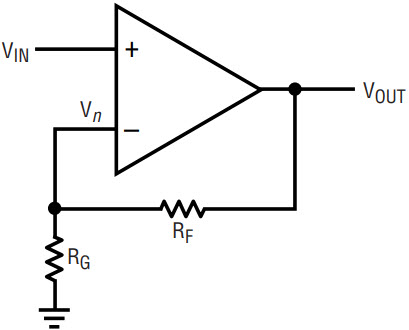
Figure 3. Noninverting gain topology.
For a voltage feedback amplifier, we can see from inspection of Figure 3 that

Combining equations 5, 1 and 2 (and assuming (1+ RF/RG)/A0 << 1), we get the closed-loop transfer function:

where

is the closed-loop bandwidth.
For a current feedback amplifier, we know that the topology of the input stage ensures that Vn = VIN. With this in mind, we can see from inspection of Figure 3 that

Combining equations 8, 3 and 4 (and assuming RF/Z0 << 1) we get the closed-loop transfer function:

where

is the closed-loop bandwidth.
Looking at equations 6 and 9, we can see that the closed-loop gain equations are identical for a voltage feedback amplifier and a CFA. However, the closed-loop bandwidths (equations 7 and 10) are quite different. As expected, the voltage feedback amplifier (equation 7) has a closed-loop bandwidth that decreases with increased closed-loop gain such that their product is a constant.
The CFA has a closed-loop bandwidth (equation 10) with some interesting consequences. To be properly compensated, the CFA requires a specific value of feedback resistor (RF) between the inverting input and the output. The value of RF can be increased to improve stability (or lower closed-loop bandwidth) in a variety of applications, such as driving capacitive loads. The requirement of a resistor in the feedback path can preclude CFAs from being drop-in replacements for voltage feedback op amps in some classes of circuits. Active filters and integrators are good examples of this class of circuit; their implementation usually has capacitors in the feedback network. Circuits where the value of the feedback resistance may change can also be problematic for a CFA. There are often alternative circuit topologies that allow CFAs to be used in these applications. Many of these topologies are discussed in the applications section that follows.
The bandwidth (and compensation) of a CFA is totally independent of RG.1 As seen in equation 9, RG is only used to set the closed-loop gain.
Application Circuits: Comparing Voltage Feedback and Current Feedback
As seen in Figure 4, it is very common to limit the bandwidth of a conventional voltage feedback amplifier by putting a small capacitor in parallel with the feedback resistor, RF. This technique does not work with current feedback amplifiers because the capacitor lowers the impedance seen by the inverting input at high frequencies. This results in reduced phase margin, which eventually leads to oscillation. To reduce the bandwidth of an application circuit using one of the LT1395/LT1396/LT1397 CFAs, simply increase the value of the feedback resistor from the nominal 255Ω; this will lower the bandwidth and increase stability. If the capacitor was added to compensate for parasitic capacitance at the inverting input, then increasing the feedback resistor may not help. In this case, a lowpass RC filter can be placed at the noninverting input.
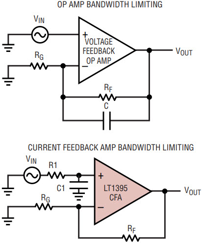
Figure 4. Bandwidth limiting.
As seen in Figure 5, an integrator is one of the easiest application circuits to make with a conventional op amp. The LT1395/LT1396/LT1397 CFAs require a slight change to the conventional topology to make sure that the inverting input always sees a resistance; simply add a resistor between the inverting input and the other passive elements.
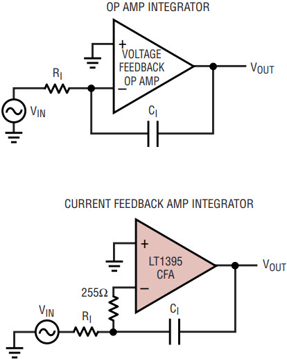
Figure 5. Integrators.
The summing amplifier seen in Figure 6 has almost the same topology for voltage feedback op amps and for the LT1395/LT1396/LT1397 CFAs. The voltage feedback op amp has a series resistor added to the noninverting input to cancel the effects of bias current at the inverting and noninverting inputs. The CFA design eliminates the resistor at the noninverting input because the inverting bias current is uncorrelated with the noninverting bias current. The additional resistor would not improve DC accuracy.
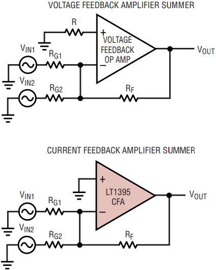
Figure 6. DC-accurate summing.
Conclusion
With the introduction of the LT1395/LT1396/LT1397 family of 400MHz current feedback amplifiers, Analog Devices offers design solutions that are often superior to those using conventional voltage feedback op amps. High slew rate, consistent closed-loop gain and a flexible output stage all merge in a family of amplifiers that are useful in a broad range of applications.
Note:
1 The actual –3dB bandwidth of a CFA falls off slightly with increased closed-loop gain. This bandwidth reduction is caused by the nonzero input impedance of the inverting input.


