


概览
设计资源
设计与集成文件
下载设计文件 1.9 M描述
The MAXREFDES1299 is a ready-to-use hardware platform for monitoring, balancing, and protecting the 4-cell battery packs in battery-powered applications such as power tools, smart devices, battery backups. Mobile devices require high-capacity rechargeable batteries to provide system power. These systems typically use lithium-ion (Li+) batteries due to their lightweight and high energy density. Every Li+ battery needs a protector to prevent damage and hazardous outcomes when subjected to abnormal voltages, current, and temperatures. Mobile devices need an accurate battery status indicator to prevent a premature or abrupt shutdown. Our fuel gauges monitor the remaining battery charge using a proprietary ModelGauge™ m5 algorithm to provide high accuracy state of charge (SOC). This reference design uses MAX17320 which monitors the voltage, current, temperature, determines battery SOC, and protects the battery from failures.优势和特点
- Monitors cell voltages, pack current, pack temperatures, balances cells, and protects by controlling charge or discharge field-effect transistors (FETs).
- Hardware protection for overcurrent in charge/discharge, short circuit in discharge, overvoltage, undervoltage, over temperature and under temperature.
- External cell balancing up to 600 mA per cell.
- I2C Interface with clock frequency of 400kHz.
所用产品
详情
The MAXREFDES1299 is a ready-to-use hardware platform for monitoring, balancing, and protecting the 4-cell battery packs in battery-powered applications such as power tools, smart devices, battery backups. Mobile devices require high-capacity rechargeable batteries to provide system power. These systems typically use lithium-ion (Li+) batteries due to their lightweight and high energy density. Every Li+ battery needs a protector to prevent damage and hazardous outcomes when subjected to abnormal voltages, current, and temperatures. Mobile devices need an accurate battery status indicator to prevent a premature or abrupt shutdown. Our fuel gauges monitor the remaining battery charge using a proprietary ModelGauge™ m5 algorithm to provide high accuracy state of charge (SOC). This reference design uses MAX17320 which monitors the voltage, current, temperature, determines battery SOC, and protects the battery from failures.
Other features include the following:
- Monitors cell voltages, pack current, pack temperatures, balances cells, and protects by controlling charge or discharge field-effect transistors (FETs).
- Hardware protection for overcurrent in charge/discharge, short circuit in discharge, overvoltage, undervoltage, over temperature and under temperature.
- External cell balancing up to 600 mA per cell.
- I2C Interface with clock frequency of 400kHz.
Applications
- Smartphones, Tablets, and 2-in-1 Laptops
- Medical Devices, Health and Fitness Monitors
- Digital Still, Video, and Action Cameras
- Handheld Computers, Radios, and Terminals
- Power Tools, Wireless Speakers, and Drones
- Smart Batteries and Battery Backup
A small size, 4-Cell Fuel Gauge using the MAX17320 is demonstrated for External Cell balancing application.
Table 1 provides an overview of the design specification.
| PARAMETER | SYMBOL | MIN | MAX |
| Battery Voltage Measurement Range | VBATT | 4.2V | 19.6V |
| Number of Cells | NCell | 2 | 4 |
| Voltage Measurement accuracy (-40&°C to 125&°C) | -12.5mV | +12.5mV | |
| Active Supply Current | 57µA | ||
| External Cell Balancing Current | 600mA | ||
| I2C Interface Clock Frequency | fSCL | 400kHz | |
| Operating Temperature range | -40&°C | 85&°C | |
| Dimensions L X W | 51mm x 51mm | ||
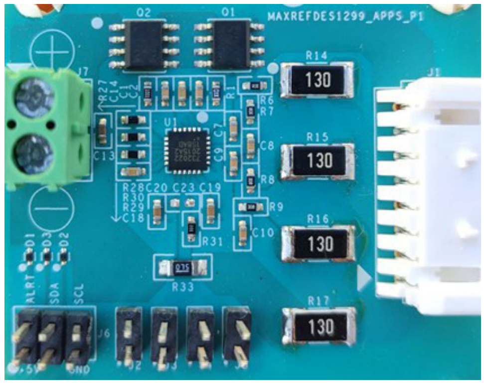
This document describes the hardware shown in Figure 1. For more details, refer to the MAX17320 data sheet and the MAX17320 EV kit data sheet. This reference design is tested using Samsung INR38650 2500mAh battery and compatible with MAX17320GEVKIT software. The SDA, SCL and the GND pins of J6 in MAXREFDES1299 must be connected to SDA1, SCL1 and DGND pins of MAX17320GEVKIT respectively to validate this design using EV kit software.
Multi-cell battery packs face a common issue of Cell Imbalance. It affects the run time and the life cycle of the entire battery pack. Cell balancing is a suitable technique to overcome this problem and allows the battery pack to operate longer. Imbalance can be diagnosed by knowing the discrepancy in cell voltages and can be corrected either instantaneously or gradually through bypass cells with external/internal circuits. Balancing is done during charge or idle time. The balancing current and the time to balance can be chosen based on the end application.
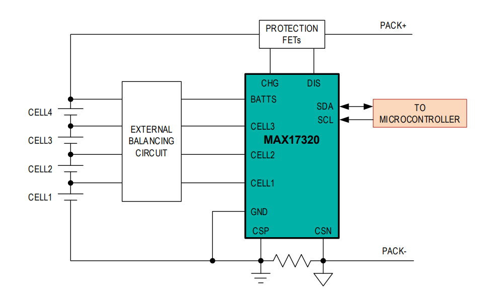
Figure 2 shows the block diagram of MAXREFDES1299. In this design, external cell balancing is implemented for higher balancing current of 600mA at 4V.
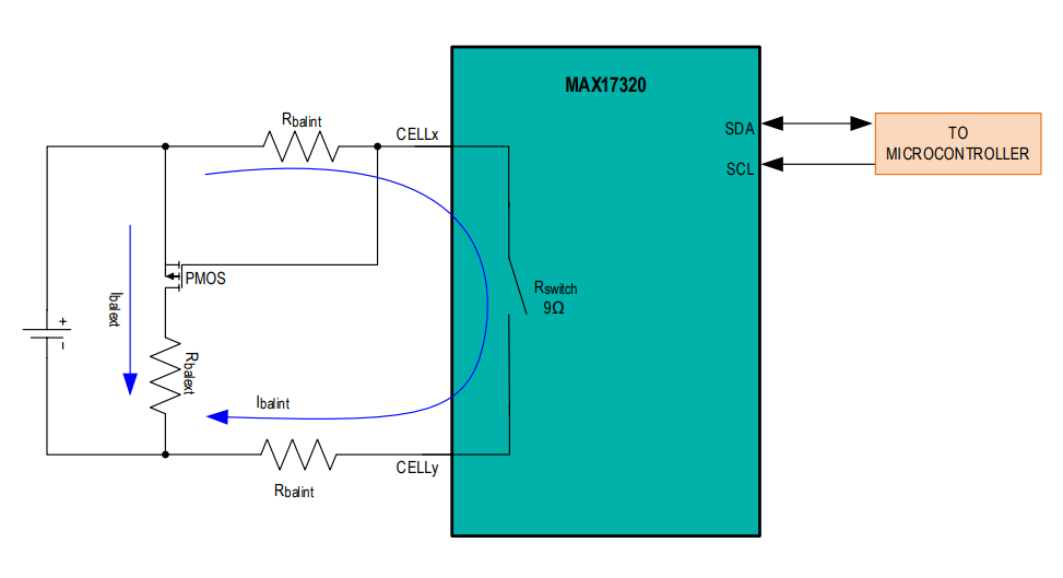
Larger balancing current is required to balance the cells at a faster rate. The internal balancing switch supports maximum up to 100mA of balancing current. An external balancing circuitry is required for greater than 100mA balancing current. An external circuitry with P-FET and resistor is designed and shown in Figure 3. When cell balancing is enabled, and the cell balancing conditions are met, the internal switch turns ON and allows the current to flow through the Rbalint and Rswitch (9Ω typical). This current is limited by the sum of these resistors. When the internal cell balancing switch is ON, the voltage across the Rbalint is applied to the Gate to Source terminals of the external balancing switch (P-FET), causing it to turn ON and thus allows the external balancing current to flow through the external balancing resistor Rbalext.
The series resistors Rbalint on the CELLX and CELLY pins must be selected to limit the internal balancing current.
From Figure 3, Ibalint and Ibalext current equations can be derived as,
Equation (1)
Equation (2)
Where,
Ibalint is the internal balancing current
Ibalext is the external balancing current
Rswitch is 9Ω typical
Vcellmax is the maximum cell voltage during charging
Rbalint is the series resistor to limit internal balancing current
Rbalext is the external balancing resistor
This section describes how to select Rbalint, P-FET and Rbalext for the cell balancing.
Step 1: Rbalint Selection
To avoid the IC getting heated up during cell balancing, Rbalint resistors are designed for low internal cell balancing current. The value of these resistors should be selected to limit the internal cell balancing current to 100mA, the maximum rated current for these pins. In MAXREFDES1299, Rbalint resistors are designed for 1mA internal cell balancing current. From equation (1), for Vcellmax of 4.2V, the Rbalint can be calculated as follows,
From Equation (1),
A standard 2kΩ is selected for this design.
Power dissipation through Rbalint:
So, Rbalint of 2kΩ with power rating of 0.063W is chosen in this design for an internal balancing current of 1mA.
Step 2: Rbalext Selection
In MAXREFDES1299, the external balancing resistor Rbalext is designed for a balancing current of 600mA.
From Equation (2),
Power Dissipation through 7Ω resistor
= 0.6A x 0.6A x 7Ω = 2.52W
In this design, two parallel resistors of 13Ω each with a 2512, 2W package are chosen as a trade-off between the design solution size and Rbalext power dissipation.
Current through each 13Ω resistor
Power Dissipation through 13Ω resistor
= 0.3A x 0.3A x 13Ω = 1.17W
Step 3: P-FET Selection
When the internal cell-balancing switch is turned ON, Rbalint and (Rswitch + Rbalint) form a resistor-divider, generates a voltage of nearly Vcellmax /2 across the 2kΩ resistor. The voltage drop across the resistor is nearly 2.1V. Therefore, P-FET with Gate to Source threshold voltage less than 2.1V must be selected for proper turn on.
In MAXREFDES1299, to handle the rated balancing current of 600mA, TrenchFET SI1317DL-T1-GE3 with VGS(th) of 0.8V is selected due to its low on-resistance and low Qg and Qgd.
文件和资源
-
MAXREFDES1299 Design Files2021/9/22ZIP1M
-
MAXREFDES1299: 4-Cell Fuel Gauge with External Cell Balancing using MAX173202021/9/22PDF310K
支持与培训
搜索我们的知识库,获取技术问题答案。我们专门的应用工程师团队也会随时为您解答技术问题。