
MAXREFDES1153


概览
设计资源
描述
The MAXREFDES1153 is a monitoring solution for genuine lithium-ion (Li+) battery packs with 2 to 15 cells connected in series. This reference design provides an accurate state of charge (SOC) in milliamp-hours (mAh) or percentage (%), as well as precision measurements of current, voltage, and temperature for multicell battery packs. The MAXREFDES1153 features monitoring and balancing of the battery pack, as well as safety features and protection circuits that guard against conditions such as overcharging, overdischarging, and overcurrent. This reference design is a fully tested solution for power tools, uninterruptible power supply (UPS), and some industrial applications. The ModelGauge™ m5 EZ configuration or a custom battery pack model could be loaded to the MAX17205 on the MAXREFDES1153 board through microcontrollers. The MAXREFDES1153 provides samples that load the ModelGauge m5 EZ configuration or a custom battery pack model through the STM32 master board and shows the measured SOC, voltage, current, and temperature on the touchscreen of the STM32 master board. The default configuration of the MAXREFDES1153 is for 5 Li+ cells in series. An overview of the design specification is shown in Table 1.
所用产品
详情
The MAXREFDES1153 is a monitoring solution for genuine lithium-ion (Li+) battery packs with 2 to 15 cells connected in series. This reference design provides an accurate state of charge (SOC) in milliamp-hours (mAh) or percentage (%), as well as precision measurements of current, voltage, and temperature for multicell battery packs.
The MAXREFDES1153 features monitoring and balancing of the battery pack, as well as safety features and protection circuits that guard against conditions such as overcharging, overdischarging, and overcurrent. This reference design is a fully tested solution for power tools, uninterruptible power supply (UPS), and some industrial applications.
The ModelGauge™ m5 EZ configuration or a custom battery pack model could be loaded to the MAX17205 on the MAXREFDES1153 board through microcontrollers. The MAXREFDES1153 provides samples that load the ModelGauge m5 EZ configuration or a custom battery pack model through the STM32 master board and shows the measured SOC, voltage, current, and temperature on the touchscreen of the STM32 master board. The default configuration of the MAXREFDES1153 is for 5 Li+ cells in series. An overview of the design specification is shown in Table 1.
| Parameter | Symbol | Min | Min | Max |
| Input Voltage Range | VBAT | 8V | 20V | 65V |
| Battery Capacity | BATCAP | 0mAh | — | 65535 mAh |
| Number of Cells | NCELL | 2 | 5 | 15 |
| Charging Current | ICHG | 0A | — | 10A |
| Discharging Current | IDISCHG | 0A | — | 10A |
| Overcharge Protection Voltage per Cell | VOCP | — | — | 4.25V |
| Overdischarge Protection Voltage per Cell | VODP | — | — | 2.5V |
| Charge Current Protection | ICCP | — | — | 10A |
| Discharge Current Protection | IDCP | — | — | 20A |
This document describes both hardware and firmware of the MAXREFDES1153. Figure 1 shows the MAXREFDES1153 hardware, while Figure 2 presents a block diagram showing the detailed system design. This reference design has been built and tested for 5-cell configuration, details of which follow later in this document.
FIGURE 01
FIGURE 02
The MAX17205 is an excellent pack-side fuel gauge that monitors a multiple-series cell pack, playing the main role of the whole system. This fuel gauge is an ultra-low-power, stand-alone IC that implements the Maxim ModelGauge m5 algorithm without requiring host interaction for configuration. The MAX17205 provides precision measurement of current, voltage, and temperature. To prevent battery pack cloning, it integrates SHA-256 authentication with a 160-bit secret key. It also incorporates a unique 64-bit ID.
The ModelGauge m5 algorithm combines the short-term accuracy and linearity of a coulomb counter with the long-term stability of a voltage-based fuel gauge, as well as temperature compensation, to provide industry-leading fuel-gauge accuracy. This fuel gauge automatically compensates for cell aging, temperature, and discharge rate, and provides accurate SOC in mAh or % over a wide range of operating conditions. As the battery approaches the critical region near empty, the ModelGauge m5 algorithm invokes a special error correction mechanism that eliminates any error. The MAX17205 provides accurate estimation of time-to-empty and time-to-full, Cycle+™ age forecast, and three methods for reporting the age of the battery: reduction in capacity, increase in battery resistance, and cycle odometer.
Step 1: Multicell Operating Circuit
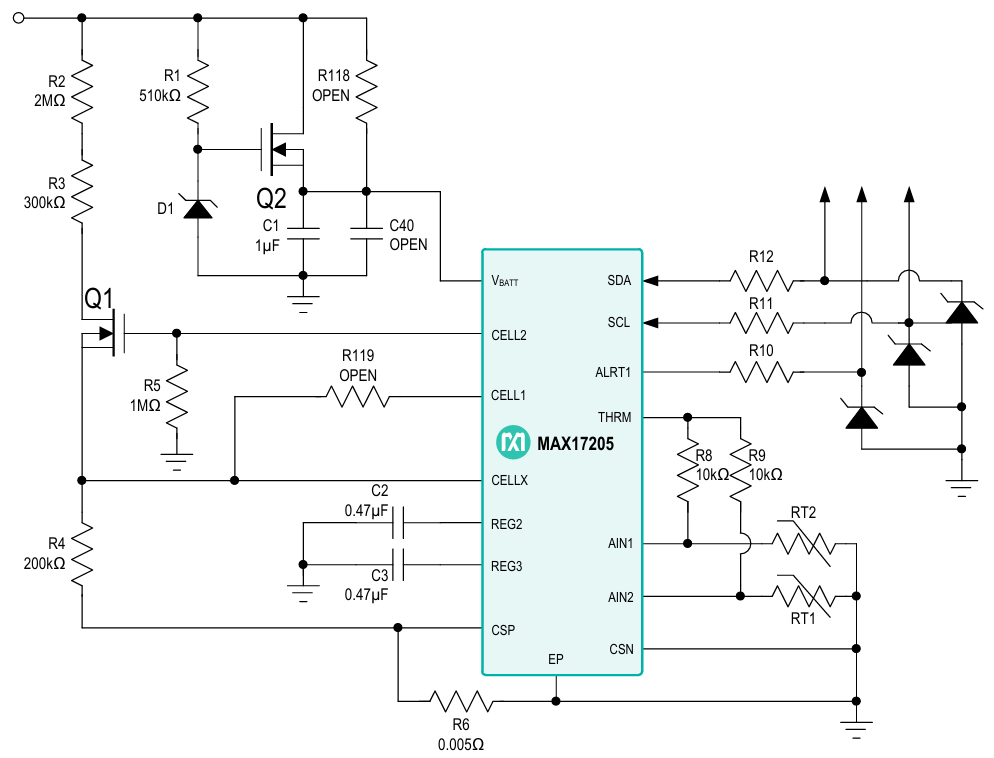
The MAXREFDES1153 can be configured for 2- to 15-cell Li+ battery packs. Figure 3 shows the schematic of the MAX17205 multicell fuel gauge. The default configuration of this design is for 5 cells in series.
The BYD Microelectronics BM3451TJDC-T28A cell battery protector is used in this design. The BM3451 works constantly to monitor each cell’s voltage, charge or discharge current, and temperature of the environment to provide protections including overcharge, overdischarge, discharge overcurrent, short circuit, charge overcurrent, and overtemperature. It also can change the protection delay time of overcharge, overdischarge, and discharge overcurrent through setting the external capacitors. The BM3451 provides external bleeding for cell-capacity balancing to avoid unbalanced capacity between each cell, which could help extend battery life.
For 6- to 15-cell battery packs, R2 and R3 should be replaced. The total value of R2 and R3 should be (2.5 × number of cells - 1) x 200kΩ.
For 2- to 4-cell battery packs, R1, R2, R3, R4, C1, D1, Q1, and Q2 should be removed first, then replace R5 with a 0Ω resistor. Next, add R118 = 50Ω, R119 = 0Ω, and C40 = 0.1µF.
For a number of cells other than 5, the circuit of cell battery protector BM3451 should be modified accordingly. See the BM3451 data sheet for details.
Step 2: External Sense Resistor Selection
Charging and discharging current is measured by an external sense resistor (RSENSE) placed between the CSP and CSN pins over a ±51.2mV range. There is no fixed rule to choose RSENSE—users are free to choose the resistor based on the measurement range and resolution. See Table 2 for details. It is recommended that the sense resistor value be stored with an LSB weight of 10µΩ, giving a range of 10µΩ to 655.35mΩ. Table 3 shows recommended register settings based on common-sense resistor values.
| Sense Resistor (CGAIN = 0x0400) (Ω) | Current Register Resolution (µA) | Current Register Range (A) |
| 0.005 | 312.5 | ±10.24 |
| 0.010 | 156.25 | ±5.12 |
| 0.020 | 78.125 | ±2.56 |
| Sense Resistor | nRSENSE Register |
| 0.005Ω | 0x01F4 |
| 0.010Ω | 0x03E8 |
| 0.020Ω | 0x07D0 |
Host software can use the nRSENSE register value to convert current and capacity information into mA and mAh.
Table 4 shows the resolution and range of registers described hereafter. Note that the current and capacity values are displayed as a voltage and must be divided by the sense resistor to determine amps or amp-hours. It is strongly recommended to use the nRSENSE (1CFh) register to store the sense resistor value for use by host software.
| Register Type | LSB Size | Minimum Value | Maximum Value | Notes |
| Capacity | 5.0µVh/RSENSE | 0.0µVh | 327.675mVh/RSENSE | Equivalent to 0.5mA with a 0.010Ω sense resistor. |
| Percentage | 1/256% | 0.0% | 255.9961% | 1% LSB when reading only the upper byte. |
| Voltage | 0.078125mV | 0.0V | 5.11992V | — |
| Current | 1.5625µV/RSENSE | -51.2mV/RSENSE | 51.1984mV/RSENSE | Signed 2’s complement format. Equivalent to 156.25µA with a 0.010Ω sense resistor. |
| Temperature | 1/256°C | -128.0°C | +127.996°C | Signed 2’s complement format. 1°C LSB when reading only the upper byte. |
| Resistance | 1/4096Ω | 0.0Ω | 15.99976Ω | — |
| Time | 5.625s | 0.0s | 102.3984h | — |
Step 3: Detailed Description of Firmware
The host demo software that works as an interface between the MCU (STM32) and the MAXREFDES1153 is not included in this reference design. Contact technical support if demo software is required. Features of the demo software include an I2C interface for chip access, quick model loading functions, and a simple INI file loading tool.
Initialization
At IC power-up, the fuel gauge retrieves battery model parameters from nonvolatile memory without host software interaction. The MAXREFDES1153 firmware offers two ways to change models: a quick model loading function and an EZ mode function.
Quick Model Loading Function
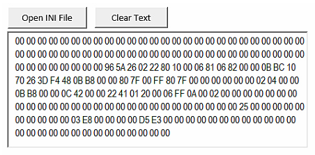
This function helps customers to load the “INI” file into MAX17205. This consists of two steps: 1) using “INI” file transfer tool, 2) utilizing host sample code to load the data string. With the “INI_Stream” tool, users can transform the INI file into a data stream. The host sample code then transfers the data stream to the chip through a UART interface, rearranging the stream into a resistor setting and loading to the chip. Figure 4 shows the panel of the “INI_Stream” file—simply click “Open INI File” button and choose a file; the stream will show in the text bar below.
The UART setting provides the flexibility to use any serial port tool to establish communication between PC and the MCU board. Settings for the current demo are as follows:
- Baud Rate: 9600bps
- Data: 8-bit
- Parity: None
- Stop: 1-bit
- Flow Control: None
The PC must send the data stream in hex format.
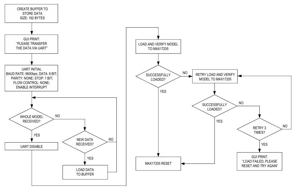
The data stream sent by the PC is stored within the microcontroller in a temporary area. After loading the model to the MAX17205, this temporary area will be released. Figure 5 shows the host microcontroller process to load the model.
EZ Model Function
ModelGauge m5 EZ performance provides plug-and-play operation for the MAX17205. While the MAX17205 can be custom-tuned to the application’s battery through a characterization process for ideal performance, it has the ability to provide reasonable performance for most applications without requiring custom characterization. Though the EZ mode provides good performance for most cell types, some chemistries such as lithium iron phosphate (LiFePO4) and Panasonic® NCR/NCA series cells require a custom model characterization for best performance.
ModelGauge m5 EZ is designed to be used without any initial setup. Simply connect a relaxed battery to the evaluation kit (EV kit) or custom PCB and begin reading the registers of interest. However, accuracy can be improved with minimal configuration using the Configuration Wizard in the MAX17205EVKIT GUI. The EV kit software can be used without the hardware to generate the appropriate configuration values. The following standard parameters should be adjusted in the Configuration Wizard:
- Label Capacity: DesignCap
- Empty Voltage: VEMPTY
- Charge Termination Current: ICHGTERM
- Pack Configuration: PackCfg
- Sense Resistor: RSENSE
Note that the EZ mode settings are very flexible to accommodate different designs. The EZ mode functions in this firmware are based on the MAXREFDES1153 hardware design, which is a multicell battery pack solution using an external protection and balancing circuit. However, more EZ mode settings are available.
Figure 6 shows the diagram of the host microcontroller process used to configure the MAX17205 in EZ mode.
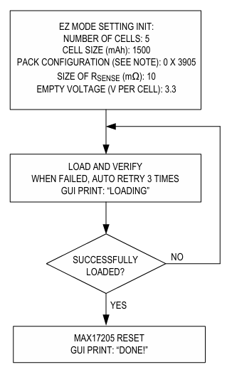
Note: The nPackCfg setting is based on the hardware design. The setting guide is provided in the firmware; see MAX17205.h→nPackCfg Setting.
2-Wire/I2C Functions for MAX17205
The I2C functions shown in Table 5 are needed in the model load, EZ mode, and output processes.
| Features | Parameter | Detail |
| Void WriteRegister(uint16_t reg, uint16_t value) | reg: addr of register value: value to write | Write value to register. No return. |
| uint16_t ReadRegister(uint16_t reg) | reg: addr of register | Read value from register. Return read data. |
| int WriteVerifyReg(uint16_t reg, uint16_t value) | reg: addr of register value: value to write | Write value to register and verify. Automatic retry 3 times if write failed. Return 1 for success. Return 0 for failure. |
| int WriteVerifyModel(uint8_t* pbuffer) | pbuffer: location where the model is kept | Load model to the MAX17205 and verify. Return the number of registers that is not properly loaded. |
| void WriteModel(uint8_t* pbuffer) | pbuffer: location where the model is kept | Load model to the MAX17205 without verify. Work as block write; no return value. |
| void MAX17205_Reset_Chip() | — | Software reset of the MAX17205. Automatic 200ms waiting period for chip reset. No return. |
| void MAX17205_Load_NV() | — | Load model into nonvolatile memory and reset firmware. Automatic 200ms waiting period for chip reset. |
| uint16_t MAX17205_RemainNV_Times() | — | Read remaining memory write times. Return remaining times. |
| int MAX17205_EZ_Mode(EZ_setting cfg) | EZ setting structure including configuration, RSENSE, empty voltage, design cap size, total number of cells | Load EZ mode configurations to the MAX17205. Return 0 if loaded successfully. Return number of registers that are not properly loaded. |
文件和资源
-
MAXREFDES1153 Design Files2021/3/11ZIP3 M
支持与培训
搜索我们的知识库,获取技术问题答案。我们专门的应用工程师团队也会随时为您解答技术问题。