Design Note 429: Tiny Amplifiers Drive Heavy Capacitive Loads at Speed
Introduction
Parasitic capacitance lurks behind every corner of an electronic circuit. FET gates, cabling, ground and power planes all add to the Farad bottom line. When the capacitive load gets heavy in high speed circuits, careful op amp selection is paramount for optimizing slew rate, current output capability, power dissipation, and feedback loop stability.
Demanding Circuit Requirements
For example, consider a 100MHz, 2VP-P sine wave signal driving a 350pF capacitive load. The minimum required slew rate without distortion for this scenario is:

The slew rate sets the maximum output current—the amplifiers are charging a capacitor, so the maximum output current occurs at maximum slew.

Maximum power dissipation is an important consideration. For an op amp operating from ±5V supplies, and assuming the capacitive load starts at 0V and is charged at maximum current, peak power is:

With a package that has a thermal resistance of 135°C/W, this much continuous power would result in a 148°C rise in die temperature. If the ambient temperature is 85°C, this brings the die to a package-melting 233°C!
To isolate CLOAD from the amplifier, a design could use a series resistor, RS . This technique ultimately limits bandwidth when the resistor or capacitive load gets very large. The bandwidth reduction associated with this RC time constant may limit performance. With a current feedback amplifier, increasing the feedback resistor, RF, is an alternative compensation method to reduce peaking.
Tiny Current Feedback Amplifiers
For the high speed, large capacitive load example above, the 400MHz LT1395/LT1396/LT1397 family of current feedback amplifiers certainly satisfies the slew rate requirement. The LT1395/LT1396/LT1397 can process large signals with speed and 80mA minimum guaranteed output current. However, for the example above, this amplifier family falls short of the 220mA requirement. In this case one may not be enough, but four certainly are. Paralleling these amplifiers satisfies current requirements while maintaining safe power dissipation and stability.
The LT1397 quad was designed to push big loads of current while maintaining good thermal properties. The copper underbelly of the tiny 4mm × 3mm DFN package brings the thermal resistance down to 43°C/W, and a die temperature rise above ambient of only 47°C for the given example.
Component Selection and Testing
Without assembling the entire parallel configuration, a single-amplifier test circuit can be constructed to check results into the load capacitance divided by the number of amplifiers to be used, CLOAD/4.
The remaining task is to select appropriate values of the feedback resistor (RF) and series resistor (RS) to maximize he –3dB bandwidth and sufficiently minimize the amount of peaking in the frequency response. For both RF and RS, smaller values result in both additional bandwidth and increased peaking. RF has a practical lower limit of about 255Ω. As load capacitance increases, RF and/or RS values must increase to maintain stability.
Figure 2 shows measurement results using the 4-amplifier circuit of Figure 1 with various RF/RS combinations and 350pF of total load capacitance. Measurements were performed at a gain of 1, so RG was not used.

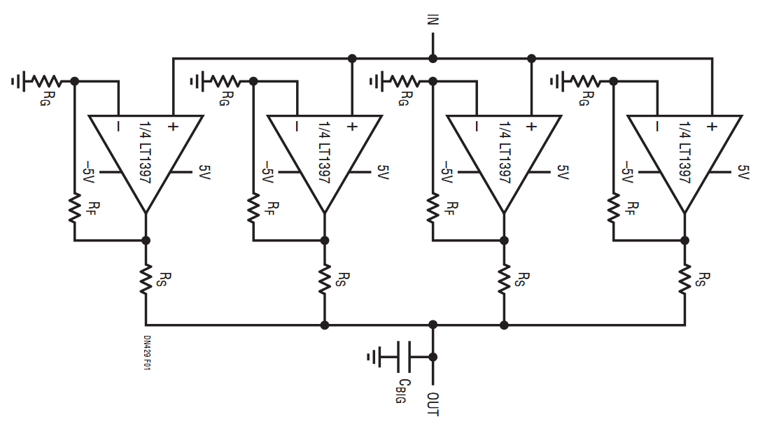
Figure 1. Using All Four Amplifiers of the LT1397 to Drive Large Capacitive Loads.

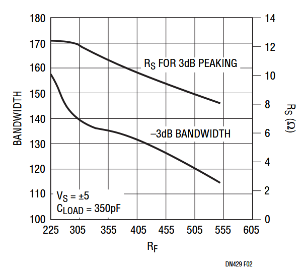
Figure 2. Selecting RF and RS to Drive 350pF When Paralleling the Four Amplifiers of the LT1397.
The effectiveness of the 4-amplifier circuit topology over a single amplifier can be seen in Figure 3. For a more representative effect the load capacitance was tripled to 1000pF. The paralleled 4-amplifier circuit is capable of slewing 4V into 1000pF in under 10ns. This corresponds to a slewing output current of 400mA. The single amplifier current limits at about 140mA, reducing the slew rate into this large capacitive load. The same 4V swing for the single requires 28ns, almost three times longer than the 4-amplifier configuration.

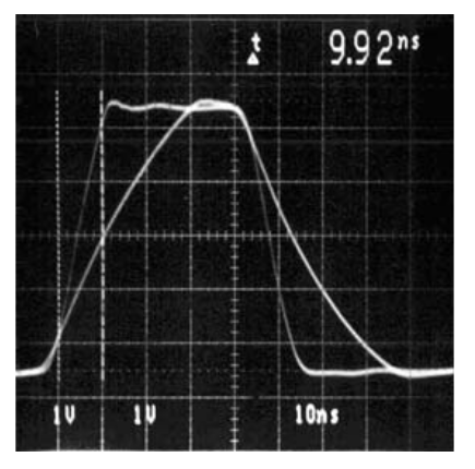
Figure 3. Four Amplifiers Out-Race One Amplifier When Driving a 1000pF Capacitive Load. The Response Time of the Single Amplifier Lags the Quad by a Factor of Three.
Conclusion
Always consider using all of the amplifiers available in a tiny power-enhanced package to provide the muscle needed to rapidly slew heavy capacitive loads. Also consider current feedback amplifiers such as the LT1397 to make it easy to control a very wide bandwidth circuit.
作者
