Design Note 193: SMBus Accelerator Improves Data Integrity
Introduction
The System Management Bus (SMBus) is gaining popularity in portable computers as a communication link between smart batteries, the battery charger and the power management microcontroller. The convenience of this simple 2-wire bus is prompting designers to use it for communication with other peripherals such as battery selectors, backlight controllers, temperature monitors, power switches and other devices. Before long, the SMBus will become what its creators envisioned—a general purpose system management bus that connects various low speed peripherals throughout a portable computer (see Figure 1).
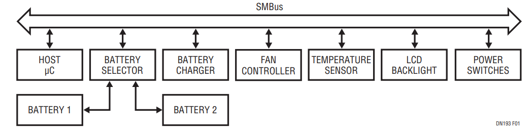
Figure 1. SMBus Applications in a Notebook Computer.
The SMBus uses the open-drain I2C® protocol for its physical layer, with respecified logic thresholds and pull-up current. Whereas the I2C bus allows pull-up currents as high as 3mA, the SMBus has been specified with a maximum pull-up current of only 350μA. The maximum 400pF bus capacitance allowed by I2C is reduced to only 50pF because of the low pull-up current provided by the SMBus. Although the lower logic thresholds specified for SMBus peripherals mitigate the rise time problem, most SMBus systems include devices with I2C CMOS logic thresholds that can be as high as 0.8 • VCC (microcontrollers are a good example). All it takes is one such peripheral with high logic thresholds, and SMBus rise times can seriously restrict bus capacitance.
The SMBus rise time problem can result in data integrity problems, or in severe cases, cause the bus to stop operating entirely. Because 50pF can easily be exceeded with just a few feet of cable, SMBus systems often fail to operate reliably when simply connected together on the lab bench. The problems of SMBus capacitive loading can become worse when more peripherals are connected by long traces running throughout a portable computer.
The Solution
Linear Technology developed the LTC1694 SMBus Accelerator active pull-up circuit to alleviate the SMBus rise time problem. This SOT-23 packaged part simply replaces the two external pull-up resistors and reduces the SMBus rise time by a factor of 3× to 4×. Figure 2 compares an SMBus signal rise time using a standard resistor pull-up to a signal produced with the SMBus accelerator. SMBus systems that work unreliably (or not at all) with the minimum value pull-up resistor perform as intended with the LTC1694.
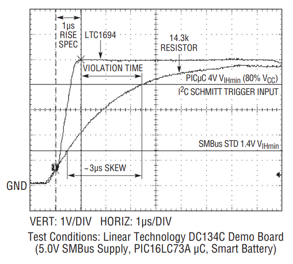
Figure 2. SMBus Open-Drain Signal Rise Times.
Figure 3 is a functional block diagram of the LTC1694 SMBus accelerator. Two identical pull-up circuits are contained within the LTC1694: one for the clock line (SCL) and one for the data line (SDA). When both open-drain signals remain high (SMBus idle), the LTC1694 provides a 100μA pull-up current to each line to keep them in the high state. When either signal is pulled low by an SMBus driver, the pull-ups source approximately 275μA. Because this pull-up current is less than the 350μA allowed by the SMBus specification, the logic low (VOL) level on the bus is reduced, resulting in improved low state noise margin.
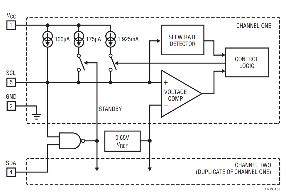
Figure 3. LTC1694 Functional Block Diagram.
The biggest improvement occurs when an SMBus driver releases the open-drain signal. If the signal voltage exceeds 0.65V and the positive slew rate exceeds 0.2V/μs, then a 2.2mA pull-up current source is activated in the LTC1694. This 2.2mA current source quickly pulls the signal high until it hits the supply rail. After a short delay the current is reduced to the 100μA level with the signal at a steady state high level. Noise immunity is also built into the slew rate detector to avoid false tripping on narrow noise spikes. In essence, the LTC1694 provides light pull-up when the open-drain signal is static or falling, but accelerates the rising edge once a rising signal is detected.
Making the Upgrade
Retrofitting an existing SMBus system is easy—the LTC1694 simply replaces the two pull-up resistors. PCB area is approximately the same, owing to the small 5-pin SOT-23 package. Because SMBus peripherals may operate from either 5V or 3.3V, the LTC1694 is designed to operate equally well from either supply voltage. The SMBus accelerator powers down to only 60μA when both SMBus signals are high, so impact on battery life is also insignificant.
SMBus data integrity is vital, especially since Lithium-Ion battery charge control may be communicated via the bus. It’s not always obvious that “flaky” SMBus operation is the result of excessive rise time, but the test is easy to implement—simply replace your pull-ups with the LTC1694.
作者
