PC Printer Port Controls Data Logger
Engineering projects often require measurements over an extended period of time. A commercial data logger or pen plotter will do the job, but those instruments are expensive. As an inexpensive alternative (Figure 1), you can combine a simple, 4-channel data-acquisition circuit with a tool available to most engineers: the personal computer or PC. The PC also lets you manipulate data in spreadsheets and incorporate it into reports.

Figure 1. This 4-channel data logger obtains power and control signals through the printer port of a PC. The PC can present the data as a plot or a list, or route it to a file for later analysis.
One of the computer's printer ports controls the data logger and provides 5V power. Five volts also powers the charge-pump voltage inverter (IC1) that produces a local -5V supply. The negative supply current is small, so simple RC filters at IC2 and IC4 are adequate for reducing the charge pump's switching noise. (Similar filters on the 5V supply reduce the effect of noise from the PC.) This circuit draws only 220µA.
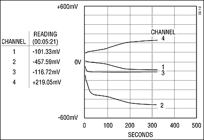
A QBASIC program (available from Maxim) lets the system sample and display as many as four channels, both as present readings and as plots with time indicators (Figure 2). Or it can write the data to a file for later evaluation. QBASIC is available with MS-DOS on most PCs. Though fairly slow, it easily accommodates different tasks, more channels, different scaling, etc., and makes data calculations such as the minimum, maximum, and average. Minimum cycle time for reading the four channels is one second, and the graphics output is scaled for a VGA monitor with 640 x 480 resolution.

Figure 2. The program output can track four channels as shown.
The A/D converter is a 15-bit multi-slope device (MAX132), which (in this application) gives a resolution of about 15µV. It includes a serial interface for data and control signals, and four digital outputs (P0-P3) for controlling multiplexers and other peripherals.
IC2 provides a reference voltage of 2.5V, scaled as required to optimize line-frequency rejection in the A/D converter: 655mV for 50Hz lines, or 545mV for 60Hz lines. Software senses the state of pin 12 in the printer connector (jumpered as shown for a 50Hz or 60Hz line frequency) and adjusts the A/D converter's integration time accordingly.
The TEST STROBE is a pulse at the start of each set of readings. Present on pin 7 of the 25-pin printer connector, it simplifies debug and troubleshooting operations by serving as a trigger for the oscilloscope.