Measuring the output current of the MAX38908 Linear Regulator
Abstract
The MAX38908 is one of Analog Device's next generation LDOs designed to improve output noise and Power Supply Rejection Ratio (PSSR) over existing solutions. In some applications, there is a need to measure the output voltage/current. In some systems, it is not always feasible to measure the current on the input side as this affects accuracy and places unwanted requirement on the number of analog-to-digital converters and single-ended input channels.
Introduction
The MAX38908 is a high-performance low-dropout (LDO) capable of providing up to 4A of output current depending on the application with regards to the input and output voltage ratio. Traditionally, LDOs use a single voltage control loop, and in some cases employ a feed-forward capacitor to improve stability and load response time. The Power Supply Rejection Ratio (PSSR) very much relies on the ratio of the Open Loop and Closed Loop Gain. To improve the PSSR over conventional LDO topologies, Analog Devices employs a proprietary topology that includes more than one control loop. This application note outlines the correct way to measure output current. To sense output current without incurring load regulation errors, the current-sense resistor must be placed inside the voltage sense feedback. The MAX38908 contains more than one control loop, one of which uses the BYPASS CAP to provide feedback. In normal applications, the BYPASS CAP must be connected to the OUT pins of the MAX38908 (Figure 1).

Figure 1. Application circuit for MAX38908.
Circuit Configuration to Measure MAX38908 Output Current
To maintain load regulation, the voltage feedback network must be placed on the output side for the current sense resistor. To maintain the PSSR benefit from the MAX38908, the Bypass Cap must also be placed on the output side of the current-sense resistor (Figure 2b). Avoid configuration 2a.

Figure 2a. Incorrect configuration.

Figure 2b. Correct configuration.
PSSR Performance
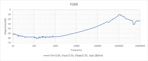
To illustrate the improper way to configure the MAX38908 to measure current, a PSSR test was performed on the circuit in Figure 2a. The PSSR degrades considerably at the higher frequencies (Figure 3).
Conditions: VIN = 3.6V, VOUT = 3.3V, VBIAS = 5.3V, IOUT = 280mA, COUT = 22µF, RSENSE = 0.33?.

Figure 3. PSSR with incorrect current-sense configuration.
The circuit is then reconfigured (Figure 2b) and the PSSR improves dramatically (Figure 4).

Figure 4. PSSR with correct current-sense configuration.
Transient Load Step Measurements

Figure 5. Transient response 0A to 2A load step (with current-sense resistor).

Figure 6. Transient response 0A to 2A load step (without current-sense resistor).
Summary
Measuring the current output from the MAX38908 using a current-sense resistor inside the feedback loop is an easy way to measure output current without degrading load regulation, PSSR, or stability. Although a simple technique, it is important to follow these guidelines for the MAX38908.