How to Configure the DS1852 Alarm and Warning Thresholds to Comply with SFF-8472
Abstract
The purpose of this application note is to explain how to configure the DS1852 so that the Alarm and Warning Thresholds comply with the memory location requirements of the SFF-8472 standard.

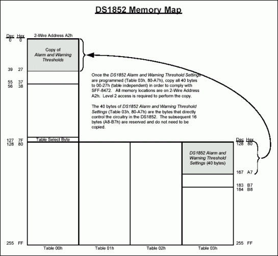
Figure 1. DS1852 memory map.
DS1852 Alarm and Warning Thresholds and the SFF-8472 Standard
The SFF-8472 standard dictates the requirements for diagnostic monitoring interfaces of optical transceivers. The standard requires that the alarm and warning threshold limits of an optical receiver be stored in memory locations 00h through 37h of 2-wire address A2h. Memory locations 28h through 37h of that range are reserved per the standard.
However, the Alarm and Warning Thresholds of the DS1852 reside at memory locations 80h to A7h (Table 03h), also at 2-wire address A2h. The DS1852 uses the thresholds in these registers to configure the alarm and warning circuitry. Therefore, in order to comply with the standard, the DS1852 Alarm and Warning Thresholds must be copied into the location specified by the standard (see Figure 1). The problem is solved by simply copying the values to the required location solely at the cost of several extra 2-wire transactions during factory calibration/testing. As Figure 1 illustrates, ensure that Level 2 access is obtained before the copy is performed. Likewise, keep in mind that for a particular module if the Alarm and Warning Thresholds are ever changed, both locations must be written to.
Conclusion
The DS1852 Alarm and Warning Thresholds can easily be made to comply with SFF-8472 by copying the values from the DS1852 locations to the SFF-8472 specified locations.