Hot-Surface Warning Light Requires No External Power
Abstract
Using a thermoelectric generator (TEG) to sense the temperature of a surface and a step-up switching regulator to boost the TEG output to a useful level, this warning circuit flashes a high-brightness LED when the surface temperature exceeds a threshold.
A similar version of this article appeared in the February 4, 2008 issue of Machine Design magazine.
Because a hot-surface warning light affects personnel safety, it must operate reliably whenever the surface is hot. Heat, however, complicates the light's power source, because high-temperature power wiring is difficult to install and not very flexible, and high-temperature batteries (hard to procure) require frequent maintenance. A better approach is a self-powered warning device that takes its power from the heated environment.
Semiconductor junctions can convert electricity to heat, and vice versa. Passing current through a thermoelectric cooler (TEC), for instance, heats one side of the junction and cools the other: a phenomenon known as the Peltier effect. Conversely, by exploiting the Seebeck effect, a thermoelectric generator (TEG) creates a voltage across a junction (and an electric current if the circuit is closed) when one side is forced hot and the other remains cold.
TECs and TEGs are essentially the same. Being reversible from a thermoelectric point of view, TEGs can perform as TECs and vice-versa. Both consist of a large number of pn junctions, connected electrically in series and thermally in parallel, forming a thin semiconductor wafer that is bonded between thin ceramic wafers to enhance the heat transfer. TEGs are made with higher-temperature materials (up to 200°C), and are optimized for electricity generation. On the other hand, the maximum temperature to which TECs can be exposed is about 100°C.
The voltage output from a TEG depends on the temperature difference applied to its ceramic sides, and the number of internal junctions in series. This voltage is small when the temperature difference is small. Most circuits require higher operating voltages than a TEG can produce, but a step-up switching regulator with low start-up voltage can boost the TEG output to a useful level.
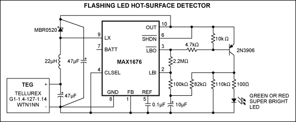
The circuit of Figure 1 employs the principles mentioned above. With the TEG attached to the monitored surface, the LED flashes whenever the surface temperature exceeds a threshold: When the monitored surface is hot enough to produce a temperature differential of about 20°C, the super-bright LED begins to flash twice per second, and keeps flashing until the differential subsides to 10°C. No external power source is required, because a step-up switching regulator (MAX1676) boosts the TEG output to about 5V.

Figure 1. When the monitored surface is hot, this step-up regulator (MAX1676) boosts the TEG's low output voltage to a level suitable for flashing the LED.
The flashing oscillator is formed by the 2N3906 transistor and a precision comparator internal to the MAX1676 (accessible via LBI and LBO). The LBI/LBO terminals are connected in a positive feedback loop that creates hysteresis at the input (where the 10µF capacitor connects to common).
Two resistors connected at the inverted-LBO output (available at the 2N3906 collector), one to common and the other to the 10µF capacitor, add a negative feedback loop with asymmetric charge/discharge paths, as required for the 2Hz, 50ms-ON flashing pulses. The pnp transistor also drives 30mA through the super-bright LED. The low operating voltage (about 5V) limits the choice of LED color to red, green, yellow, or orange. The circuit can't drive white or blue LEDs.
You should mechanically mount the TEG to maximize the temperature difference between its surfaces: a heat sink transfers heat away from one side, keeping it cool, and the other side tracks the monitored surface to which it is thermally attached (Figure 2). The TEG's output voltage is proportional to the temperature difference across it, so the circuit begins to flash when it sees a sufficient temperature differential at the TEG. Figure 3 shows the 2N3906-collector waveform present while the LED is flashing.

Figure 2. When the monitored surface in Figure 1 heats up, a heat sink minimizes temperature rise on the other side of the TEG. One side of the TEG must be in intimate thermal contact with the heat sink and the other with the hot surface. Thermal-contact compound and flat surfaces on both sides of the TEG ensure intimate thermal contacts.

Figure 3. This waveform appears at the 2N3906 collector in Figure 1.
The maximum temperature of operation, usually about 200°C, is set by the TEG's absolute maximum ratings (see data sheet). If the circuit is built on top of or very close to the TEG, then all circuit components must have adequate ratings for operating temperature. If the circuit is mounted at some distance from the TEG, the connecting wires must be rated for high temperature operation. A complete data sheet and other information on the MAX1676 converter can be found at www.analog.com.