DAC Makes Controller Programmable
Abstract
Make the output of any power supply controller or converter programmable by adding an 8-bit serial digital-to-analog converter (DAC) and a dual op amp.
Adjustable-voltage power supplies are used to power microprocessors, to conserve power while maintaining performance. Long used in computers, this idea is now seeing wider application in other microprocessor-based products.
Some specialized power-controller ICs accept a digital code and produce the corresponding output voltage. This is effective, but often more than what is required for a particular application.
As an alternative, you can make the output of any power supply controller or converter programmable by adding an 8-bit serial digital-to-analog converter (DAC) and a dual op amp (Figure 1).
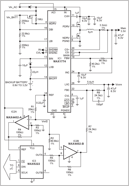
Figure 1. A DAC and dual op amp (IC3 and IC2) add programmable capability to the Vcore output of this multiple-output power supply (IC1).
Some methods of voltage adjustment include a digital pot in the resistor-divider feedback path, but that approach allows the voltage to go only as low as the feedback voltage (Vfb). The output range for this circuit, on the other hand (0V to 2Vfb), is perfect for most processor core voltages.
The multiple-voltage power supply IC1 has many features useful to handheld devices, but it doesn't provide for DAC control of its Vcore output. Its feedback voltage for Vcore at pin 22 (Vfb) is 1.0V, and its reference voltage (Vref) is 1.25V. To help reduce output-voltage error when implementing digital control, you should use the controller Vref because Vfb is derived from Vref. In this case Vref is greater than Vfb, so the resistor divider network R1/R2 is included to create a voltage (Vref2) equal to Vfb. For other controllers in which Vfb and Vref are the same, that divider is not necessary.
Op amp IC2A creates a 2V reference for the 8-bit DAC (IC3): 2Vref2 = 2Vfb = 2V. The op amp's low output impedance makes it very compatible with the DAC, whose SPI serial interface has good INL, DNL, and TUE specifications. Because the reference voltage is 2V, the DAC's output voltage can be expressed as Vo = 2V(XXX/256), where XXX is the decimal equivalent of the second half of the 16-bit binary code loaded into the DAC. (256 increments provide an approximate resolution of 8mV/step.) The first half of the code must be 02HEX, which instructs the DAC to load the A register.
The second op amp inverts the DAC output voltage about a center of Vref2. That is, 1.398V from the DAC becomes 0.602V from the op amp. That voltage creates current flow in R7, because the other end of R7 is held to the feedback voltage Vfb. That current also flows in R8, which defines the output voltage. Using the example above, 0.602V from the op amp creates a current flow of (1.0V - 0.602V)/24.3kΩ = 1.4µA, which implies an output (Vcore) of 1.0V + 1.4µA(24.3kΩ) = 1.398V. As this example shows, the Vcore output voltage is (ideally) the same as the DAC's output voltage. Vcore can be programmed from 0V to 1.992V, with typical accuracy of 3%; or better (Table 1). Using ±0.1%; resistors improves the accuracy.
| DAC Code (hex) | Desired Voltage (Volts) | Measured Voltage (Volts) |
| 02 00 | 0.000 | 0.007 |
| 02 0D | 0.102 | 0.109 |
| 02 20 | 0.250 | 0.255 |
| 02 33 | 0.398 | 0.405 |
| 02 40 | 0.500 | 0.514 |
| 02 4D | 0.602 | 0.614 |
| 02 60 | 0.750 | 0.762 |
| 02 73 | 0.898 | 0.907 |
| 02 80 | 1.000 | 1.009 |
| 02 8D | 1.102 | 1.109 |
| 02 A0 | 1.250 | 1.263 |
| 02 B3 | 1.398 | 1.380 |
| 02 C0 | 1.500 | 1.482 |
| 02 CD | 1.602 | 1.582 |
| 02 E0 | 1.750 | 1.737 |
| 02 F3 | 1.898 | 1.886 |
| 02 FF | 1.992 | 1.983 |