Design Note 226: A 24V/48V Hot Swap Controller
As supply voltages continue to drop, designers face the difficult task of minimizing the voltage drops through a distributed power system. Designers are leaning toward distributing power at a higher voltage, commonly 24V/48V, then stepping down the voltage on each board in the system to the final desired value using power modules.
Most power modules require an input bypass capacitor that is typically hundreds of microfarads in value. When the board is hot-plugged into a live power rail, the input capacitor can draw huge inrush currents as it charges. The inrush current can cause permanent damage to the board’s components and cause glitches on the system power supply that can make the system function improperly.
The LT1641 provides a simple and flexible solution to the hot swapping problems. The chip allows a board to be safely inserted into or removed from a live backplane with an operating supply voltage range from 9V to 80V. It features a programmable analog foldback current limit, programmable undervoltage lockout and overvoltage protection, automatic restart or latched operation and direct power module enable control.
Typical Application
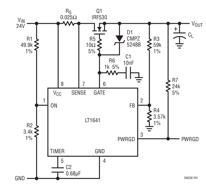
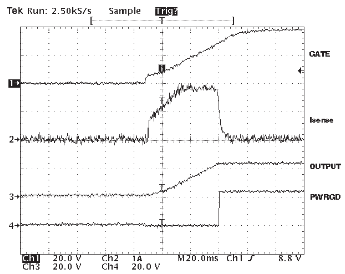
Placing an external N-channel pass transistor (Q1) in the power path as shown in Figure 1, controls power supply on a board. Resistor RS provides current detection and capacitor C1 provides control of the GATE slew rate. C2 is the timing capacitor. Resistor R6 provides current control loop compensation and R5 prevents high frequency oscillations in Q1. Resistors R1 and R2 provide undervoltage sensing. D1 clamps the VGS of Q1 at 18V and thus protects Q1 from breaking down if the DRAIN node is shorted to ground. After the power pins first make contact, transistor Q1 is turned off. If the chip detects that the input voltage is high enough, it charges the GATE pin high with 10μA. The supply inrush current is set at IINRUSH = 10μA • CL/C1. Once the voltage at the output has reached its final value, as sensed by resistors R3 and R4, the PWRGD pin goes high. The waveforms are shown in Figure 2.

Figure 1. 24V Input Voltage Application.

Figure 2. Power-Up Waveforms.
The LT1641 features a programmable foldback current limit with an electronic circuit breaker that protects against short circuits or excessive supply currents. The current limit level is set by placing a sense resistor between the VCC pin and SENSE pin. When the load exceeds the current limit, the LT1641 regulates the GATE pin voltage to keep the current through the sense resistor at a constant value. In the meantime, C2 is charged with an 80μA pull-up current. If the voltage at the TIMER pin reaches 1.233V and an overcurrent condition still exists, the LT1641 turns off the pass transistor.
To prevent excessive power dissipation in the pass transistor and to prevent voltage spikes on the input supply during short-circuit conditions at the output, the current folds back as a linear function of the output voltage, which is sensed at the FB pin. The foldback ratio is 4:1.
Automatic Restart
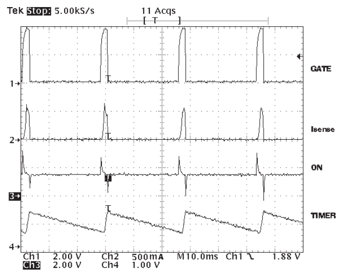
To force the LT1641 to automatically restart after an overcurrent fault, the bottom plate of capacitor C1 can be connected to the ON pin. When an overcurrent condition occurs, the GATE pin is driven to maintain a constant voltage across the sense resistor. Capacitor C2 begins to charge. When the voltage at the TIMER pin reaches 1.233V, the GATE pin is immediately pulled to GND and transistor Q1 is turned off. Capacitor C1 momentarily pulses the ON pin to low and clears the internal fault latch. When the voltage at the TIMER pin decreases to 0.5V, the LT1641 turns on again. If the short-circuit condition at the output still exists, the cycle will repeat itself indefinitely with 3.75% on-time duty cycle and prevent Q1 from overheating. The waveforms are shown in Figure 3.

Figure 3. Automatic Restart Waveforms.
