Using the Simple Serial Interface for Embedded Measurement Devices: 78M6610+LMU, 78M6610+PSU, and the MAX78630+PPM
Abstract
The simple serial interface (SSI) is a binary protocol for communicating with Analog embedded measurement devices (78M6610+LMU, 78M6610+PSU, and MAX78630+PPM).
Overview
The simple serial interface (SSI) is a binary serial protocol implemented for UART communications on Analog Devices’ embedded measurement devices (EMD). This application note addresses the features and structure of the protocol by providing a detailed description of the available commands and corresponding source code examples. The key features of the protocol are:
- Simplicity: The protocol can be implemented on host processors without absorbing excessive system resources.
- Robustness: Each packet contains a header, byte count, payload, and checksum. If the header, byte count, and checksum of a command are not all correct, the recipient can reject the packet.
- Efficiency: Data is exchanged in binary encoding rather than character-coded values, and commands do not need to be echoed to the host. Additionally, multiple commands can be sent in a single packet to further reduce the communications overhead.
- Supports multidrop systems: Target device addressability supports the connection of multiple target devices on a single serial bus.
SSI is a packet-based protocol that implements master-slave or command-response communications. Two types of packets are used in the SSI: master packets, which are issued by a host device; and slave packets, which are issued by a slave EMD in response to a command from the host or master.
Download the corresponding source code.
Serial Interface Selection
Access Analog EMDs by the master through three serial interfaces: UART, SPI, and I2C. SSI uses the UART interface and the EMD must be configured accordingly to use SSI. This is done through pullup or pulldown resistors on the appropriate pins of the device. Refer to the device data sheet for a description of configuring the serial interface of the device.
Device Address
The device address (SSID) of an EMD is set through the combination of the DevAddr register and one or two pins of the device depending on the package of the device. Refer to the device data sheet for an explanation of setting the SSID of the device.
Master Packets
A master packet always contains the following:
- A one-byte header, 0xAA
- A one-byte packet length indicator, which is the count of all the bytes in the packet including itself
- A payload, which can consist of multiple commands
- A checksum, which is the two’s complement of the modulo-256 sum of all the preceding bytes in the packet, starting with the header byte and including the last bye of the payload
From the description above, there are a few characteristics that pertain to all valid master packets:
- A master packet is always 4 or more bytes long.
- A master packet cannot be greater than 255 bytes long.
- The field byte count is one byte.
- The maximum length of a packet is limited by the slave device’s command buffer. Refer to the slave device’s data sheet for the maximum command length for that device.
Figure 1 illustrates the structure of a master packet.

Figure 1. SSI master packet structure.
Slave Packets
The structure of a slave packet varies depending on the command that the slave device receives from the master. The shortest slave packet is a single-byte response, indicating positive or negative acknowledgement of the received command. All single-byte packets implemented in SSI are shown in Table 1.
| Code | Definition |
| 0xAD | Positive acknowledgement without data is a valid command that is received and executed, but no data response is required. |
| 0xB0 | Negative acknowledgement |
| 0xBC | Bad Command is the received command that is not supported by the slave device. |
| 0xBD | Checksum error is a checksum error that is detected in the master packet. |
| 0xBF | Buffer overflow indicates that the master packet is too long. |
A slave packet containing data follows the same general structure as a master packet and comprises a header byte, byte count, payload, and a checksum as shown in Figure 2.
The header byte of a multibyte slave packet can be 0xAA (acknowledge with data) or 0xAE (auto-reporting packet). Autoreporting packets are generated by devices such as the 78M6610+PSU, which can automatically transmit measurement data at regular intervals. Because there are different headers for autoreporting data and command response data, the host can send commands and receive responses while the slave is sending autoreporting data.

Figure 2. Multibyte slave packet.
Master Commands
Most communications between an SSI master and slave involve requesting the contents of registers in the slave device and writing to those registers. A typical command sequence consists of sending a target register address to the slave and issuing a read or write command to read or write one or more registers starting with the target address. Other commands allow selecting or deselecting individual slave devices in systems with multiple slave devices on a single bus. Devices that implement autoreporting can also accept commands to change the contents of the autoreporting packet.
All master commands supported in the current version of the SSI are shown in Table 2. Note that all Analog EMDs might not respond to all commands. Refer to the device’s data sheet to determine which commands can be executed in a specific device.
| Command | Parameters | Description |
| 0xA0 | NA | |
| 0xA1 | 1 byte, address [7:0] | Set target address bits [7:0]. |
| 0xA2 | 1 byte, address [15:8] | Set target address bits [15:8]. |
| 0xA3 | 2 bytes, address [7:0], [15:8] | Set target address bits [15:0]. |
| 0xD0 | Data | Write bytes, starting at target address, set by remainder of byte count. |
| 0xD1-0xDF | Data | Write 1–15 bytes starting at target address. |
| 0xE0 | 1 byte, number of bytes | Read bytes starting at target address, requires parameter indicating number of bytes to read. |
| 0xE1-0xEF | NA | Read 1–15 bytes starting at target address, does not require parameter, uses low nibble. |
| 0xAE | NA | Install new autoreporting command. |
| The following commands are used to select and deselect target devices | ||
| 0xC0 | NA | De-select currently selected slave device |
| 0xC1-0xCE | NA | Select target device, does not require parameter, uses low nibble. |
| 0xCF | 1 byte, SSID of device | Select target device, requires parameter indicating SSID of slave device |
Timeouts
When a device is idle (i.e., waiting for a packet from the master or target), the receive buffer pointer is reset and pointing to the first buffer location. When the first byte is received, the device checks to see if it is an SSI header or an acknowledge (0xAA). If so, the timeout timer is reset, and each subsequent receive byte also resets the timer. If no byte is received within the timeout interval and the packet is perceived to be incomplete, the device goes back to idle without sending anything. At this point, the master can resend the last command or send a new command.
Timeouts can occur when a packet is corrupt or no target is selected. Both master and slave devices must implement timeouts. A timeout occurs when during the reception of a packet no byte is received for approximately 50 byte times at the current baud rate. Masters should wait at least this amount of time before resending a command.
SSI Source Code and Examples
The following examples were developed to assist with the understanding of the SSI protocol and to lay a foundation on which to build custom applications. The provided source code does not perform any particular application; however, it does provide the basic functions needed to interface with a Analog EMD. The provided source code files and their descriptions are listed in Table 3.
| File | Description |
| maxim_ssi.c | Function definitions for SSI read, write, etc. |
| maxim_ssi.h | Function prototypes and SSI command #defines |
| maxim_em_device.h | Header file defining embedded measurement device used in application |
| 78M6610_LMU.h | Embedded measurement device header file |
| 78M6610_PSU.h | Embedded measurement device header file |
| MAX78630_PPM.h | Embedded measurement device header file |
| hw.c | Customer’s hardware specific function definitions (ssi_tx_byte, ssi_rx_byte) |
| hw.h | Customer’s hardware specific function prototypes |
maxim_ssi.c and maxim_ssi.h
The header file maxim_ssi.h provides the SSI function prototypes and defines the master commands, slave responses, and maximum packet length.
The following functions are provided by maxim_ssi.c:
- unsigned char ssi_get_checksum(unsigned char cnt, unsigned char × data)
The function ssi_get_checksum() calculates the appropriate checksum for the SSI packet. - int ssi_send_packet(unsigned char byte_cnt, unsigned char x payload)
The function ssi_send_packet() expects the payload byte count and a pointer to the payload as its arguments. If the packet byte count (payload byte count + 3) is greater than the MAX_PACKET_LEN defined in the slave device header file, ssi_send_packet() will return -1 to indicate a failure. If not, the function finishes building the packet by adding the header, packet byte count to the front of the payload and then calls ssi_get_checksum() to add the checksum to the end of the packet. The function then sends the packet a byte at a time to ssi_tx_byte().
All of the remaining functions provided by maxim_ssi.c call ssi_send_packet() and provide the basic functionality needed in an embedded measurement application. However, the end user is free to build custom packets and call ssi_send_packet() from their application. If they choose to do so, it is important to remember that the function expects only the number of bytes in the payload as its arguments and a pointer to that payload. The header, actual packet byte count, and checksum is added by the function. - int ssi_deselect_device(void)
The function ssi_deselect_device() builds the appropriate SSI payload for sending the DE_SELECT_TRGT (0xC0) master command on the serial bus and then calls the function ssi_send_packet() . The function returns either the slave device response or -1 to indicate a failure.
Call this function at the beginning of any application to ensure that no device is selected before continuing. Figure 3 shows the expected master packet and slave response from calling the ssi_deselect_device function.
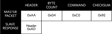
Figure 3. Master packet and slave response for deselecting a device using ssi_deselect_device.
- int ssi_select_device(unsigned char ssid)
The function ssi_select_device() expects a single byte as its argument, the SSID of the slave device to be selected. The function then builds the appropriate SSI payload for sending the SELECT_TRGT (0xCF or 0xC1–0xCE) master command on the serial bus and then calls the function ssi_send_packet() . The function returns either the slave device response or -1 to indicate a failure. Figure 4 and 5 show the expected master packet and slave response from calling ssi_select_device() the function.

Figure 4. Master packet and slave response for selecting a device with SSID > 14 using ssi_select_device.

Figure 5. Master packet and slave response for selecting a device with SSID ≤ 14 using ssi_select_device.
- int ssi_set_rw_adrs(emd_register_t adrs)
The function ssi_set_rw_adrs() expects an enumerated type of emd_register_t as its argument. This data type represents the word address of the embedded measurement device’s register. The argument can either be the name of the register defined in the associated slave device’s header file or the integer representation of the word address.
The function builds the appropriate SSI payload for sending the RW_ADRS (0xA3) master command and then calls the function ssi_send_packet(). The function returns either the slave device response or -1 to indicate a failure. Figure 6 shows the expected master packet and slave response from calling the ssi_set_rw_adrs() function.

Figure 6. Master packet and slave response for setting read/write address using ssi_set_rw_adrs.
- int ssi_clear_adrs(void)
The function ssi_clear_adrs builds the appropriate SSI payload for sending the CLEAR_ADRS (0xA0) master command and then calls the function ssi_send_packet(). The function either returns the slave device response or -1 to indicate a failure. Figure 7 shows the expected master packet and slave response from calling the ssi_clear_adrs function.

Figure 7. Master packet and slave response for the clear address command using ssi_clear_adrs.
- unsigned char x ssi_read_3bytes(emd_register_t adrs)
The function ssi_read_3bytes() expects the word address of the register to be read as an argument. The function builds the appropriate SSI payload to set the target address and read three bytes from that address and then calls the function ssi_send_packet(). The function returns a pointer to the response from the slave device. Figure 8 shows the expected master packet and slave response from calling the ssi_read_3bytes() function.

Figure 8. Master packet and slave response for reading three bytes using ssi_read_3bytes.
- int ssi_write_3bytes(emd_register_t adrs, unsigned char x data)
The function ssi_write_3bytes() expects the word address of the register to be written and a pointer to the data to write as its arguments. The function builds the appropriate SSI payload to set the target address and write three bytes to that address and then calls the function ssi_send_packet(). The function returns either the slave device response or -1 to indicate a failure. Figure 9 shows the expected master packet and slave response from calling the ssi_write_3bytes() function.

Figure 9. Master packet and slave response for writing 3 bytes using ssi_write_3bytes.
- unsigned char x ssi_read_Nbytes(emd_register_t adrs, unsigned char n_bytes)
The function ssi_read_Nbytes() expects the word address of the first register to be read and the number of bytes requested. The function builds the appropriate SSI payload to set the target address and read N bytes from that address and then calls the function ssi_send_packet(). The function returns a pointer to the response from the slave device. Figure 10 shows the expected master packet and slave response from calling the function ssi_read_Nbytes().

Figure 10. Master packet and slave response for reading N bytes using ssi_read_Nbytes.
- int ssi_write_Nbytes(emd_register_t adrs, unsigned char x data, unsigned char n_bytes)
The function ssi_write_Nbytes() expects the starting address of the register to be written, a pointer to the data to write and the number of bytes to be written as its arguments. The function builds the appropriate SSI payload to set the target address and write N bytes starting at the given address and then calls the function ssi_send_packet(). The function returns either the slave device response or -1 to indicate a failure. Figure 11 shows the expected master packet and slave response from calling the ssi_write_Nbytes() function.

Figure 11. Master packet and slave response for writing N bytes using ssi_write_Nbytes.
maxim_em_device.h
The header file maxim_em_device.h provides a convenient method of defining the Analog EMD being used in an application for those developers that might be using some or all of the devices in their applications. The file simply has #defines that can be commented or uncommented depending on the device being used.
78M6610_LMU.h, 78M6610_PSU.h, MAX78630_PPM.h
The header files 78M6610_LMU.h, 78M6610_PSU.h and MAX78630_PPM.h provide aliases for the registers of the embedded measurement device being used through the use of an enumerated type emd_register_t making the users application code human readable. Additionally, bit masks for device registers are provided.
hw.c and hw.h
The file hw.c provides the function ssi_tx_byte() and ssi_rx_byte(). This is the appropriate file for the user to implement their hardware specific function calls. The function init_hardware() can be used are removed at the users discretion; it is provided as a convenience only.
Conclusion
The simple serial interface of Analog Devices’ EMDs is true to its name: simple. This application note and the accompanying source code were written for clarification of the protocol and to get applications up and running in as little development time as possible.