AN-7625: Layout Considerations For Using The MAXM22510/MAXM22511 In Space-Constrained Applications
Abstract
The MAXM22510/MAXM22511 transceiver modules can be used in space-constrained applications that require less than 2.5kVRMS isolation with the following layout considerations.
Introduction
The MAXM22510 and MAXM22511 are complete, stand-alone isolated RS-485/RS-422, full-duplex, transceiver modules that transfer data signals and power over a 2.5kVRMS galvanic isolation barrier. For applications that are space-constrained but require less than 2.5kVRMS isolation, these devices represent an attractive solution. This application note describes PCB layout considerations when using these transceivers in applications that require a minimum PCB footprint with reduced creepage and clearance due to less than 2.5kVRMS isolation rating, rather than the design rules for full 2.5kVRMS isolation with the associated creepage and clearance requirements.
LGA Package
The MAXM22510 and MAXM22511 include a digital isolator and logic die, a RS-485 transceiver die, ceramic chip capacitors, and an integrated transformer inside of the LGA package. All of the components within the IC are encapsulated by a mold compound to form a flat surface at the top-side of the package.
Inside the package, similar to a PCB, multiple substrate layers are used on each side of the IC and all of the components within the package are connected to these substrates with adhesive epoxy, with A-side and B-side substrates separated by a gap. The bottom of the MAXM22510/MAXM2251 is coated with a dark solder mask only, without any mold compound. Figure 1 shows a simplified cross-section of the substrates and the internal components of the device.

Figure 1. Simplified cross-section of the MAXM22510/MAXM22511.
It is important to note that the base of the LGA package is not plastic, unlike conventional digital isolator packages such as SOIC or QSOP. Instead, the base of the LGA package is substrate layers coated with solder mask. Extra care must be taken to ensure that the isolation barrier beneath the IC is wide enough to meet isolation requirements.
Isolation Barrier Considerations
Layout Considerations for Full Isolation (2.5kVRMS)
On the underside of the MAXM22510/MAXM22510, there is a 4mm (typ) gap between the two substrate layers on either side of the IC. This gap is sufficient to support the 2.5kVRMS (60 sec), VISO, isolation level for which the part is rated. The operation and survivability for the MAXM22510/MAXM22511 have been verified on PCBs with the creepage and clearance boundaries of 8mm to guarantee this level of isolation.
To achieve the rated isolation voltage (VISO), the isolation barrier (dISO) under the IC must be at least 4mm wide and centered under the midline of the IC package, matching the gap between the substrates (Figure 2). Analog Devices recommends tolerance of ±200µm be applied to the isolation barrier gap width calculations.

Figure 2. Cross-section of sample layout for the MAXM22510/MAXM22511 for 2.5kVRMS isolation.
While dISO must be at least 4mm for the rated 2.5kVRMS isolation, PCB layout requirements for individual applications may require a wider isolation barrier in the PCB to achieve optimum performance under all operating conditions.
Space-Constrained Applications Requiring Lower Isolation Rating (<2.5kVRMS)
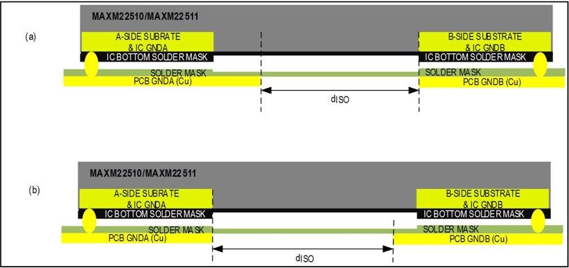
As fully integrated modules, the MAXM22510/MAXM22511 are attractive for use in size-constrained applications that require less than 2.5kVRMS isolation. In these applications, some of the PCB ground planes may be pulled under the IC, and the isolation barrier under the IC may be smaller than the 4mm gap between the A-side and B-side substrates mentioned above. Figure 3 shows two possible layouts where a PCB ground plane has been pulled under the IC and dISO < 4mm.

Figure 3. Cross-sections of sample PCB layouts for the MAXM22510/MAXM22511 for <2.5kVRMS isolation.
Note: The silkscreen and solder mask are not reliable insulators on PCB boards, and any PCB ground plane pulled under the IC reduces the width of the isolation barrier gap, in turn reducing the isolation rating of the PCB itself. As the gap between the PCB ground plane and the IC substrate on the opposite side of the isolation barrier (dISO) is reduced, the isolation capability of the board, itself, comes to define the overall isolation level of the circuit.
Although, pulling the PCB ground planes under the IC does not damage or compromise the transceiver performance of the MAXM22510/MAXM22511. The PCB designer must ensure that the creepage and clearance of the board meet the system design requirements per the regulating standard(s) for the design, which are dictated by the system's isolation rating, pollution rating, and material group, etc.
Boards must be tested and verified to meet the system isolation requirements for the end application.