AN-2624: The Slide-Switch Functionality of MAX77659 in Presence of a Valid Charger
Introduction
The MAX77659 is a compact, high-efficiency integrated solution for battery charging and power supply in low-power applications where both size and efficiency are essential. This IC includes a dual-input single-inductor multipleoutput (SIMO) buck-boost regulator, which generates one charging rail and three independently programmable power rails using a single inductor, optimizing the overall solution size.
There are two inputs to the MAX77659. The primary purpose of these input signals is to generate a wake-up signal for the power management integrated circuit (PMIC) that turns on the regulators. One of the inputs of the MAX77659 is a configurable On-key (nEN) that is compatible with both push-button and slide-switch designs. The nEN is an activelow internally debounced digital input that typically comes from the system’s on-key. Another input is the charger. When CHGIN is valid (CHGIN_OK=1) and debounced, the device transitions from standby state to resource on state (refer to the Top Level On/Off Controller State Diagram in the MAX77659 data sheet).
However, when the nEN is configured as a slide switch, with the switch in the OFF position and the MAX77659 is powered through the charger (CHGIN valid and debounced), a toggling behavior is observed on the PMIC output rails. This is undesirable in use cases where the slide switch acts as the On-key, as it may lead to momentary power loss in the downstream circuitry. This application note explains this behavior and provides potential workarounds to prevent the toggling phenomenon.
nEN Dual Functionality: Push-button vs. Slide-switch
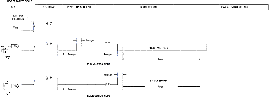
The nEN digital input can be configured to work with a push-button (CNFG_GLBL.nEN_MODE = 0) or a slide-switch (CNFG_GLBL.nEN_MODE = 1). In both push-button and slide-switch modes, the on/off controller looks for a falling edge on the nEN input to initiate a power-up sequence. The following timing diagram shows nEN’s dual functionality for power-on sequencing and manual reset. The default configuration of the device can be either push-button mode (CNFG_GLBL.nEN_MODE = 0) or slide-switch mode (CNFG_GLBL.nEN_MODE = 1) with OTP options.
When the part is in resource-on state, nEN works as a manual reset input for the on/off controller. The manual reset function is useful for forcing a power-down in case communication with the processor fails. If the nEN is configured as push-button and nEN is deasserted (nEN = LOW) for an extended period (tMRST), the on/off controller initiates a power-down sequence. If the nEN is configured as slide-switch and input is deasserted (nEN = HIGH) for an extended period/tMRST, the on/off controller initiates a power-down sequence and goes into standby mode.
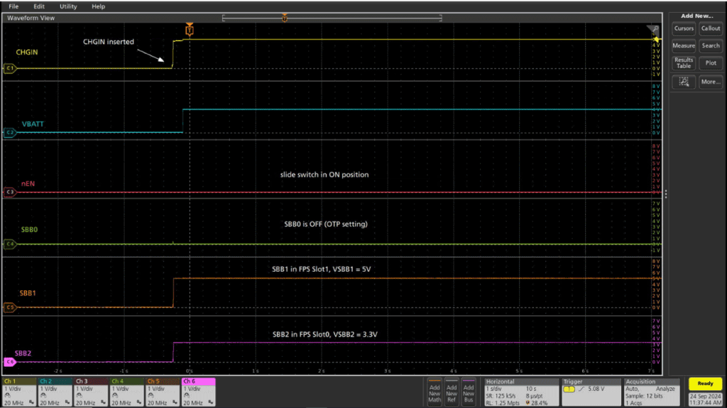
When the nEN is configured as slide-switch with the switch in ON-position and a valid CHGIN is present, the SIMO output channels and the low-dropout (LDO) output transition to resource-on state. They follow the timing diagram as shown in Figure 1.
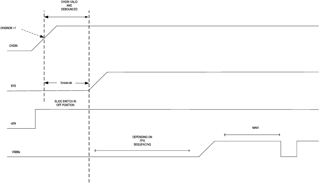
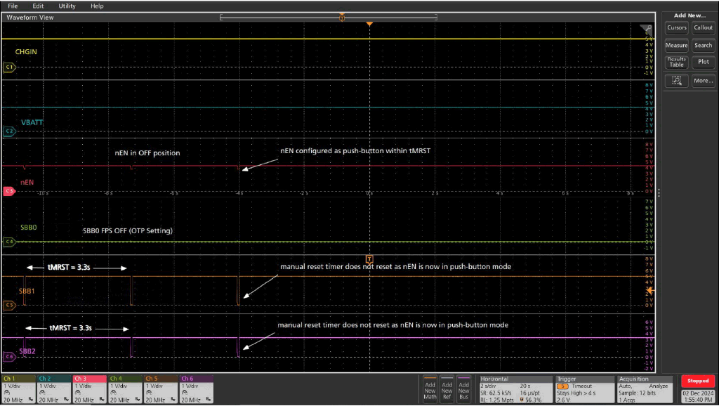
However, when nEN is configured as slide-switch with the switch in OFF position and a valid CHGIN present, the slideswitch functionality is different. CHGIN is a valid enable signal for the part to transition from standby to resource-on state (refer to transition 6 of the Top Level On/Off Controller State Diagram in the MAX77659 data sheet). After the flexible power sequencer (FPS) power-up sequencing is completed and tMRST time elapses, manual reset is triggered. This causes the part to transition from resource-on to standby state and ERCFLAG.MRT flag is set (refer to transition 8A of the Top Level On/Off Controller State Diagram in the MAX77659 data sheet). As the CHGIN is still valid and debounced, FPS power-up sequencing is initiated again and the part transitions to resource-on state from standby state. This toggling behavior of the channels after every tMRST period continues if the slide-switch is in OFF position as shown in Figure 3.
Workaround for the Toggling Behavior of SIMO Output Channels and LDO Output Rail in Slide-switch Mode (Off Position)
Using an External FET to Control nEN Signal
In slide-switch mode, the state machine looks for a falling edge on the nEN signal. When the switch is forced to be in OFF position, the nEN signal is pulled up to VCCINT through an internal pull-up resistor (RnEN_PU). This results in the state machine not capturing the falling edge on nEN within the manual reset time. This triggers the manual reset after tMRST (manual reset timer) period, forcing all outputs to transition from resource-on to standby state (refer to transition 8A of the Top Level On/Off Controller State Diagram in the MAX77659 data sheet). After transitioning to standby state because of a reset, to allow the device to power-up again, internal wake-up flags are set to remember the wake-up request. Since the CHGIN is still inserted (one of the internal wake-up flag events), the outputs again transition from standby state to resource-on state (refer to transition 6 of the Top Level On/Off Controller State Diagram in the MAX77659 data sheet).
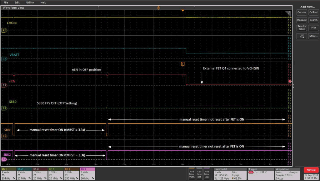
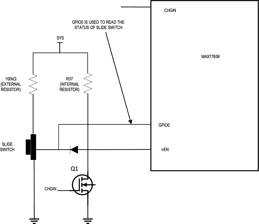
To prevent this repeated toggling of the SBBx rails and the LDO output at every tMRST period, a recommended solution is to use an external field-effect transistor (FET) (Q1) to control the nEN signal. The configuration of Q1 is shown in the following figure.
When CHGIN is valid and debounced, Q1 is ON. Q1 pulls nEN low, irrespective of the position of the slide-switch (on/off). The tMRST is not triggered, and the outputs do not toggle. When CHGIN is removed, the part is powered by the battery (BATT) and the outputs can now be toggled on and off using the slide-switch position.
To avoid a large amount of current flowing through Q1, connect an external pull-up resistor (100kΩ) from SYS pin to position 1 of the slide-switch mode (see Figure 4).
This workaround ensures that the outputs are not toggled every tMRST period by forcing nEN low. However, the slideswitch functionality (on/off) only works when VCCINT switches its power from VCHGIN to VBATT.
Use External FET to Control nEN Signal and Read Status of Slide Switch through GPIOx Pin
In addition to implementing an external FET, the GPIOx pin can be used to read the status of the slide switch. This ensures that the external microcontroller is updated with the position of the slide switch (see Figure 6).
With the knowledge of the status, the microcontroller can use I2C commands to change the enable control of the individual output channels to force them OFF if necessary.
Switch the nEN Enable Input to Push-Button Mode within tMRST
An alternative workaround to prevent toggling behavior is to change the nEN enable input from slide-switch mode to push-button mode within the tMRST period. When the slide switch is in the off position and nEN is configured as a push button, the part does not transition to the standby state, and the outputs remain in the resource-on state. It is important to note that nEN should be configured as a push button before the tMRST timer expires to prevent the outputs from powering down.
This configuration can be implemented by setting CNFG_GLBL.EN_MODE[3] = 0. For additional information on this register, refer to the Register Map section of the MAX77659 data sheet.
Conclusion
In conclusion, when the nEN pin is configured as a slide switch with the switch in the off position and a valid CHGIN signal is present, the MAX77659 exhibits a toggling behavior that transitions the output rails between the standby and resource-on states. This is caused by the manual reset timer/tMRST resetting the device and triggering the outputs to toggle after every tMRST period. To prevent this unwanted toggling, one of the solutions is to implement an external FET (Q1) to control the nEN signal. By pulling nEN low when CHGIN is valid, Q1 prevents the manual reset from being triggered, thereby ensuring that the outputs remain stable. The outputs can be toggled manually using the slide switch only once CHGIN is removed and the system is powered by the battery. The addition of an external pull-up resistor ensures proper operation without excessive current flow through Q1, and this workaround allows the slideswitch functionality to work effectively once the system switches power from charger to the battery. An alternative workaround discussed in this application note to prevent toggling behavior is to change the nEN enable input from slide-switch to push-button mode within the tMRST period. With the slide switch in off position and nEN set to push button, the MAX77659 does not enter standby, and the outputs remain in the resource-on state. It is important to ensure nEN is configured as a push button before the tMRST timer expires to avoid powering down the outputs.
