AN-1247: Software Configurable 14-Bit Quad Channel Unipolar/Bipolar Voltage Output Using the AD5734 DAC
Circuit Function and Benefits
This circuit provides, unipolar and bipolar data conversion using the AD5734BREZ, a quad, 14-bit, serial input, unipolar/ bipolar voltage output DAC and the REF192ESZ precision 2.5 V voltage reference. The only other external components needed for this 14-bit DAC circuit are decoupling capacitors on the supply pins and reference input, leading to savings in cost and board space. This circuit is well suited for closed-loop servo control applications.
Circuit Description
| Product | Description |
| AD5734 | Complete quad, 14-bit, serial input, unipolar/bipolar voltage output DAC |
| REF192 | Precision 2.5 V voltage reference |
The AD5734 is a digital-to-analog converter that offers guaranteed 14-bit monotonicity, integral nonlinearity (INL) of ±4 LSB, 0.1% total unadjusted error (TUE), and 10 μs settling time. The AD5734also integrates reference buffers and output amplifiers, which leads to additional savings in both cost and board space. Performance is guaranteed over the following supply voltage ranges: AVDD supply range from +4.5 V to +16.5 V and AVSS supply range from −4.5 V to −16.5 V. AVSS can be connected to 0 V if only unipolar outputs are required. The output range can be individually programmed for each output channel. The options are 0 V to +5 V, 0 V to +10 V, 0 V to +10.8 V, −5 V to +5 V, −10 V to +10 V, and −10.8 V to +10.8 V. The input coding is user selectable twos complement or offset binary for a bipolar output (depending on the state of the BIN/2sCOMP pin). Coding is straight binary for a unipolar output. Figure 2 shows that the typical output error of this circuit at 25°C ambient temperature is less than 0.06 %FSR.

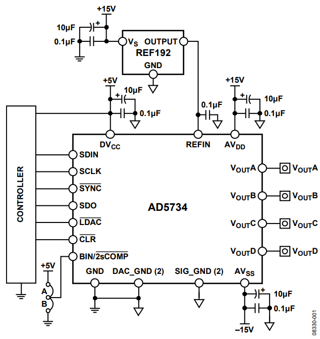
Figure 1. Unipolar/Bipolar Configuration of the AD5734 DAC (Simplified Schematic).

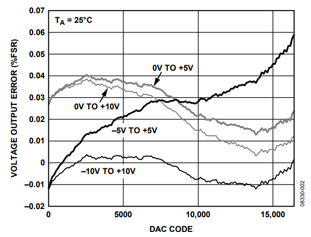
Figure 2. Output Voltage Error.
The circuit must be constructed on a multilayer PC board with a large area ground plane. Proper layout, grounding, and decoupling techniques must be used to achieve optimum performance (see MT-031 Tutorial and MT-101 Tutorial).
Learn More
Kester, Walt. 2005. The Data Conversion Handbook, Chapter 3 and Chapter7. Analog Devices.
MT-015 Tutorial, Basic DAC Architectures II: Binary DACs. Analog Devices.
MT-031 Tutorial, Grounding Data Converters and Solving the Mystery of AGND and DGND. Analog Devices.
MT-101 Tutorial, Decoupling Techniques. Analog Devices.
Voltage Reference Wizard Design Tool.
Data Sheets and Evaluation Boards
AD5754R Evaluation Board (Compatible with AD5734).