AN-064: How to run a linear motor with ADI Trinamic's TMC4671
The TMC4671 hardware controller performs Field Oriented Control (FOC) for two-phase stepper motors and for three-phase permanent magnet synchronous motors (PMSM) and it supports linear motor control.
Why use TMC4671 for linear motor servo control? The TMC4671 provides hardware closed loop torque control, velocity control, and position control even for linear motors decoupling motor control from application.
Linear Motor and TMC4671
When using the TMC4671 to control a linear motor the servo control modes torque control, velocity control, and position control for three-phase permanent magnet synchronous motors (PMSM) are applicable. To close the loop the TMC4671 provides an ADC engine, as well as multiple position feedback options which can be configured to the linear motor.
Linear Motor with Incremental Encoder Feedback
In this architecture a linear incremental encoder (ABN) provides the feedback for commutation/torque as well as velocity and position control.


Linear Motor Configuration
The table below gives an overview on the most important registers to configure the TMC4671 for a linear motor:
| Address | Register Name | Function |
| 0x1Bh | MOTOR_TYPE_N_POLE_PAIRS | set motor type and number of pole pairs. |
| 0x50h | VELOCITY_SELECTION | selection of velocity signal source |
| 0x51h | POSITION_SELECTION | selection of position signal source |
| 0x52h | PHI_E_SELECTION | selection of electrical angle used for commutation by FOC |
| 0x25h | ABN_DECODER_MODE | ABN encoder mode (direction, ABN pulse polarities and handling) |
| 0x26h | ABN_DECODER_PPR | ABN encoder positions per revolution, PPR =lpr · 4 |
In the following a guideline for the configuration is given.
Motor Type and Pole Pairs
The TMC4671 supports several motor types such as one phase, two phase as well as three-phase motors. Depending on the selected motor in register MOTOR_TYPE_N_POLE_PAIRS (0x1Bh) the PWM output for the gatedrivers are selected accordingly. The pole pairs define the electrical periods per mechanical period for an rotating motor. For a linear motor the pole pair is set set to one. Thus the MOTOR_TYPE_N_POLE_PAIRS (0x1B) will be set as follows for a three-phase linear motor:
| Address | Register Name | Value |
| 0x1Bh | MOTOR_TYPE_N_POLE_PAIRS | N_POLE_PAIRS = 1 (number of pole pairs) MOTOR_TYPE = 3 (three phase BLDC) |
Result: The electrical revolution equals the mechanical revolution matching a linear motor. The FOC is using three-phase control scheme.
Feedback Selection
The feedback selection registers define the type of the position feedback (e.g., digital hall, analog hall, incremental encoder,...) For a linear motor with an ABN incremental encoder the TMC4671 is configured as follows:
| Address | Register Name | Value |
| 0x50h | VELOCITY_SELECTION | 3 (phi_e_abn) |
| 0x51h | POSITION_SELECTION | 3 (phi_e_abn) |
| 0x52h | PHI_E_SELECTION | 3 (phi_e_abn) |
Result: Primary ABN encoder interface (pins 33, 34, 35) of the TMC4671 is used as feedback for torque, velocity and position mode.
2.4 Encoder Resolution
The encoder feedback selected in the Feedback Selection chapter 2.3 will be used for commutation. For correct commutation it is important to set the encoder feedback resolution (ABN_DECODER_PPR, 0x26) which is defined by pulses per electrical period. For a linear motor the electrical period covers exactly the magnet pole pair distance as depicted in figure 2:
The encoder resolution is determined by linear encoder resolution and magnetic pole pair length of the linear motor:
ABN_DECODER_PPR = pole pair length / linear encoder resolution (1)
Example: A linear motor with a pole pair length of 3cm and a linear encoder resolution of 1µm results in ABN_DECODER_PPR (0x26) = 30000.
The TMC4671 supports encoder resolutions up to 2 24 − 1. The ABN decoder count is mapped to the mechanical angle PHI_M in the range of 0... 65535. As mentioned in section 2.2 the mechanical angle PHI_M is equal to the electrical angle due to the polepair count = 1.
2.5 Encoder Initialisation
A linear incremental encoder does not provide information on the absolute motor position within an electrical period. The purpose of the encoder initialization is to obtain a known motor position within its electrical period. For a linear motor the electrical period equals the pole pair length. To initialise an encoder the wizard in the TMCL-IDE provides several inbuilt functions.
For the linear motor with only incremental feedback the encoder initialization mode 0 is suitable. Principle is to align the motor into a known position by applying a defined magnetic field. For this initialization method the linear motor should be able to move one pole pair. The resulting motor position is then well defined as it is the beginning of the electrical period thus the commutation angle can be set to zero as shown in figure 3:
Figure 3: Encoder initialization mode 0 principle

 i
i

The encoder function is implemented in the TMCL-IDE and in the TMC4671 API function tmc4671_doEncoderInitializationMode0()
2.6 Linear Scaling Factor
To map from internal units to linear units (e.g. one micrometer) a linear scaling factor is introduced which translates between electrical period and linear position.
For a linear motor (as depicted in figure 1) the linear scaling factor is determined by the pole pair length in µ m:
linear scaling factor = pole pair length[µm] (2)
Linear scaling unit is µm / mechanical revolution with the mechanical revolution being equal to one.
Example: A magnetic pole pair length of 3cm results in a linear scaling factor of 30000 µm mechanical revolution.
With this scaling factor one position step will be equal to one micrometer.
The linear scaling factor is implemented in the TMC-API and available in the TMCL-IDE. It is not part of the TMC4671 registers.
3 Linear Motor Setup with TMCL-IDE and Wizard
3.1 TMC4671 Evaluation Board
The ADI Trinamic evaluation boards are being used as an exemplary hardware platform for this application note. Following parts are used:
- TMC-45671 EVAL
- TMC-6100 EVAL (powerstage)
- TMCL-IDE
- Linear motor with an incremental linear encoder (ABN)
- pole pair length = 3cm
- linear encoder resolution = 1µm
3.2 Overview
Configuration by TMCL-IDE wizard
- Motor and pole pairs
- Motor current ADC
- Encoder (resolution and initialization)
Configuration with TMCL-IDE tools
- Feedback Selection
- Linear Scaling Factor
- PI tuning
- Position mode
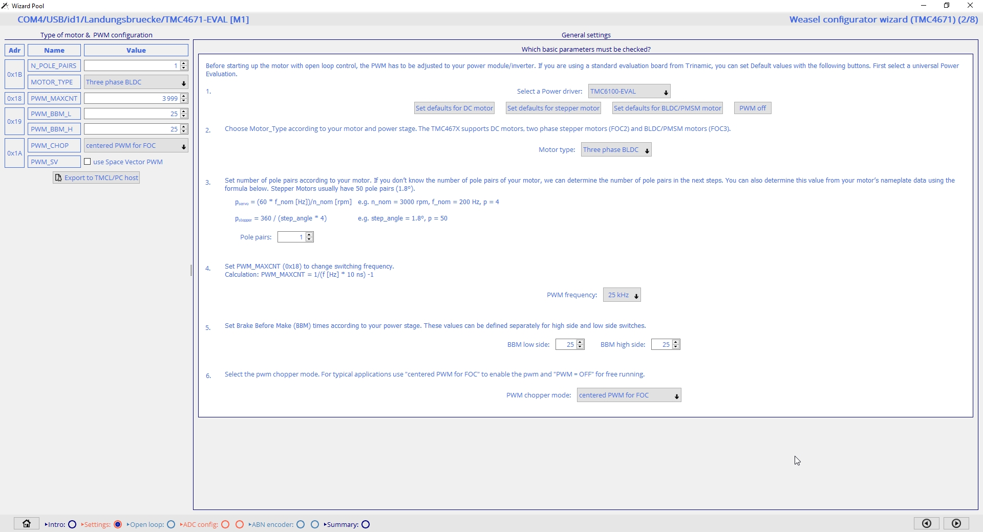
3.3 Open TMC4671 Wizard


3.4 Wizard Selection

3.5 Settings
Set number of pole pairs = 1 for the linear motor.
3.6 Open Loop
Run the motor in open loop for ADC and encoder configuration.

3.7 ADC config


3.8 ABN encoder
Init with offset estimation (Wizard) or init with offset estimation (Firmware).

3.9 Encoder Test Drive (Torque Mode)

3.10 Save Configuration
On the summary page choose ABN encoder for a preconfigured script. This will include the encoder alignment (mode 0) Then save the script using the Export Script button.

3.11 Feedback Selection


3.12 Linear Scaling Factor
Clear the position and enable linear scaling factor.


3.13 PI Tuning

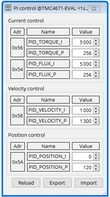
For PI tuning refer to the PI tuning appnote.
3.14 Position Mode


Position mode test run:


4 Additional Resources
- TM4671 product page
- TMC4671 PI tuning appnote
- Driving a linear stage with TMC4671
- TMC4671 API on github
- TMC4671 Python resources