目标
在本次实验中,我们将继续讨论运算放大器(参见上一次实 验“ADALM2000简单运算放大器”),并重点关注可变增益/压控放大器。
大多数运算放大器(op amp)电路的增益水平是固定的。但在很多情况下,能够改变增益会更有优势。一个简单的办法是在固定增益的运放电路输出端连接一个电位计来调节增益。不过,有时直接改变放大器电路自身的增益可能更加有用。
可变增益或压控放大器是一种根据控制电压改变其增益的电子放大器。这种电路的应用范围较广,包括音频电平压缩、频率合成器和幅度调制等。要实现这种放大器,可以先创建一个压控电阻,然后利用该电阻设置放大器增益。压控电阻是通过使 用简单偏置的晶体管可产生的众多电路元件之一。另一种方法是使用电位计来调整设置放大器增益的电阻值。
材料
- ADALM2000主动学习模块
- 无焊试验板和跳线套件
- 两个1 kΩ电阻
- 一个4.7 kΩ电阻
- 三个10 kΩ电阻
- 一个10 kΩ电位计
- 一个OP97运算放大器
- 一个2N3904 NPN晶体管
使用晶体管的压控放大器
背景知识
思考图1所示的电路原理图。


该电路的配置类似于基本的同相放大器,只增加了一个晶体管和一个与电阻R2并联的电阻。晶体管起到开关的作用,根据其当前状态(开/关)选择两种增益设置中的一种。
硬件设置
为使用晶体管的压控放大器构建以下试验板电路(图2)。


程序步骤
将第一个波形发生器用作 VIN源,向电路提供幅度为2 V峰峰值的1 kHz正弦波激励。使用第二个波形发生器控制晶体管,提供幅度为2 V的1 Hz方波激励。向运算放大器提供±5 V电源电压。配置示波器,使通道1上显示输入信号,通道2上显示输出信号。参见图3。

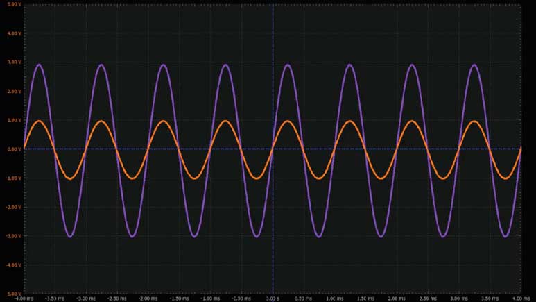
根据受控晶体管的状态,输出信号在由两个增益设置确定的两个值之间变动。
使用电位计的可变增益反相放大器
背景知识
思考图4所示的电路原理图。


在反相放大器上,用电位计取代标准反馈电阻,手动控制输出电压。
硬件设置
为使用晶体管的压控放大器构建以下试验板电路(图5)。


程序步骤
将第一个波形发生器用作VIN源,向电路提供幅度为2 V峰峰值的1 kHz正弦波激励。向运算放大器提供±5 V电源电压。配置示波器,使通道1上显示输入信号,通道2上显示输出信号。参见图6。

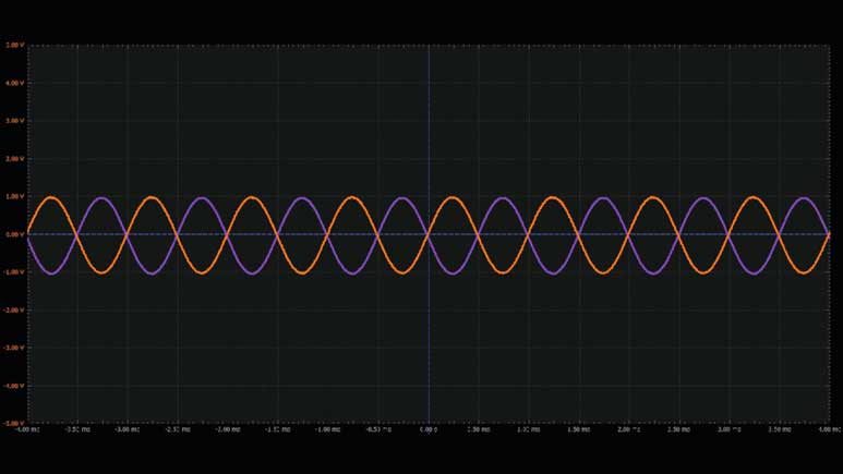
采用这种配置时,输出会反相,并根据反馈电阻值进行放大。
使用电位计的可变增益反相⁄同相放大器
背景知识
思考图7所示的电路原理图。


在这种放大器配置中,使用电位计手动控制输出电压,通过适当调节电位计来使输入反相。
硬件设置
为使用晶体管的压控放大器构建以下试验板电路(图8)。


程序步骤
将第一个波形发生器用作VIN源,向电路提供幅度为2 V峰峰值的1 kHz正弦波激励。向运算放大器提供±5 V电源电压。配置示波器,使通道1上显示输入信号,通道2上显示输出信号。参见图9。

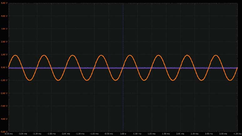
采用这种配置时,输出会被放大,并在±VIN之间变动。
问题
能否简要列举几个可变增益放大器的实际应用例子?
您可以在 学子专区论坛上找到问题答案。
