Introduction
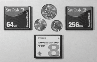
Within the past few years, we have witnessed in the consumer marketplace a proliferation of portable handheld devices supported by the use of small, high-density, removable storage media. Walk into any consumer electronics store, and you will see the array of MP3 players, digital cameras, and PDAs, boasting hundreds of megabytes of expandable offline nonvolatile storage. With this impressive storage capability, users can download their favorite MP3s or upload their newly snapped JPEG image files between the portable device and a desktop PC. My first digital camera included a strange little matchbox-sized card that could be easily ejected and used to upload all of my JPEG files to the PC. This CompactFlash™ storage card (Figure 1) has become a de facto standard for portable compact storage of multimedia files.
Today, card slots for CompactFlash exist in hundreds of digital cameras, handheld or palm-size PCs, MP3 players, voice-memo recorders, and other types of electronic equipment—including printers, heart monitors, and defibrillators—perhaps more so than any other competitive small form-factor cards. CompactFlash cards, designed to be small, removable, and durable, are offered in sizes from 8 megabytes up to 1 gigabyte.

In addition to its small size, the CompactFlash (CF) has the advantage of acting like any PC ATA (IDE) hard-disk, floppy, or zip disk drive in a Type II PC. (ATA was the standard bus interface on the original IBM AT computer and is also called IDE, for Integrated Drive Electronics.) CompactFlash supports the ATA command register set, but it is more reliable for data storage than an IDE hard disk drive, because it has no moving parts. It operates at speeds of traditional hard-disk drives, while consuming less power. Because it is ATA-compatible, it can be formatted like any hard drive or floppy diskette—as an alternative way of transferring files to or from a personal computer.
A Windows/DOS-formatted file can easily be copied from a CF card that has been removed from any ATA-compatible device (such as a digital camera or Palm™-size PC). The data on the card can be transferred to (or from) a desktop personal computer through a high-speed, low-cost CompactFlash reader/writer attached to the computer’s USB or parallel port. In fact, Windows 2000 and XP will automatically recognize a CF card inserted into a CF USB reader/writer and assign a logical drive letter to the card under Windows Explorer. Any software application then has access to it as file storage. Plug a CF card into a USB reader/writer connected to a PC, and your favorite MP3 song titles can be simply “dragged and dropped” to the card in a matter of seconds, ready for playback on a portable MP3 device. From the perspective of embedded digital signal processing (DSP), a CompactFlash is a great way to save recorded real-time digitized streams of data for temporary storage or off-line retrieval. Embedded-system designers have already begun to use them as a way to expand a processor’s limited external-address-range capabilities.
When evaluating the use of a CompactFlash, designers will often ask these questions: How difficult is it to use a CompactFlash card in my DSP-based system? How do I physically connect a CompactFlash to a DSP? Can it be interfaced without any external components or logic? How difficult is it to program an ATA interface with a CompactFlash using a DSP? Can a DSP support a FAT-16 (16-bit cluster-addressed file allocation table) file system like that of an Intel-based PC?
This article will provide details on how to design a glue-less, hot-swappable interface to a CompactFlash storage card—using the ADSP-2191M digital signal processor—for a portable MP3 player application. The ADSP-2191 is a 16-bit, 160-MIPS (million-instruction-per-second) processor, which contains 64 K-words of internal on-chip memory and a variety of memory- and industry-standard peripheral interfaces. With its low dynamic power consumption, the ADSP-2191M was designed to be used in a variety of handheld portable devices—which are likely to use a compact, high-density, removable storage medium.
The interface was developed and tested using the ADSP-2191 EZ-KIT Lite Evaluation Platform. The completed prototype was ultimately used as a reference design for a 32-bit double precision MP3 player (decoder) based on an Analog Devices ADSP-219x DSP.
CompactFlash Overview
In 1995 the CompactFlash Association (CFA) was organized to develop a common standard interface format that would enable the capture, retention, and transportation of data—such as images or audio files—among a wide variety of digital systems. This collaboration resulted in the publishing of the CompactFlash specification. It defined a compact, high-density, removable storage interface that was basically a reduced 50-pin version of the PCMCIA or PC card specification, which was also electrically compatible with an IDE-hard drive. Because it is designed to be removable, the CF card can be “hot-swapped” in an active microprocessor-based system without requiring a system power-down or hard reset. The CompactFlash standard also supports three different industry-standard interfaces: PC-Memory mode, PC-card I/O mode, and True-IDE mode. When using True-IDE mode, the device can be connected to an IDE connector without requiring any extra supporting circuitry.

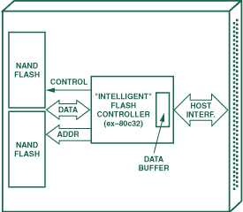
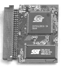
Figure 2 is a functional diagram common to a variety of CompactFlash storage cards. Hidden within the plastic casing is a small printed circuit board (Figure 3) containing a flash controller, some data-buffer memory, and flash modules. The flash controller chip executes disk-emulation software and contains some host-accessible memory-mapped registers that adhere to the ATA specification. To the host processor, the flash controller looks like a standard ATA (IDE) hard disk. The host processor (which might be a DSP) can access a set of ATA registers for command, status, and data words.

To transfer data, the host processor first loads seven ATA registers with configuration data; it then executes an operation by writing to an eighth command register. The flash controller, physically located between the nonvolatile (i.e., AND/NAND) memory chips and the external host interface, “emulates” the ATA command. The card also contains a memory buffer, which is controlled by the internal flash controller and used to transfer “sectors” (512-byte blocks) of information between the external processor and the memory chips. The flash controller is responsible for managing the interface protocol and also retrieving and placing data sectors between the external host processor and the storage memories. In addition, the flash controller handles error-correction code, performs diagnostics, identifies memory defects, and performs power-down operations when the card is in idle mode.
Using a CF Card with the ADSP-2191M
The ADSP-2191M digital signal processor (DSP) was chosen to implement an example of a functional low-cost, high-performance CompactFlash-based MP3 player, as Analog Devices already offers a commercially available double-precision 32-bit decoder design based on the ADSP-219x family. That solution was initially designed to read MP3 files from a CD drive. To demonstrate a functional glue-less, hot-swappable CF interface, we developed a modified version of the CD MP3 decoder to alternatively support CF MP3 playback using the ADSP-2191 EZ-KIT Lite evaluation board and its associated software. Figure 4 shows a block diagram of the ADSP-2191 EZ-KIT CF-based MP3 decoder system. To identify and read MP3 DOS/WIN file clusters, the ADSP-2191 also executes a simplified FAT-16 file system to identify and load MP3 files downloaded to the card from a PC.

The ADSP-2191M, a 16-bit, 160-MIPS single-chip microcomputer—optimized for digital signal processing and other high-speed applications—combines the ADSP-219x core architecture with three serial ports, two SPI-compatible ports, one UART port, a DMA controller, three programmable timers, and general-purpose I/O pins. The ADSP-2191M also integrates 64K words of on-chip memory; it thus has enough on-chip internal memory to easily integrate: an AC-97 audio driver, MP3 decoder, FAT-16 file system, low-level ATA commands, and host control commands—without requiring the use of external memory.
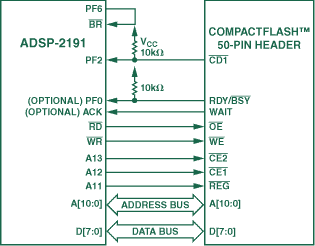
Figure 5 shows a functional block diagram of a CompactFlash 8-bit data interface to the ADSP-2191M DSP’s external memory interface (EMI) port. The CF PC Card Memory mode was selected as the mode of operation for connecting the CompactFlash to the DSP. This default mode of operation allows the ATA command/status registers to be simply memory-mapped to the ADSP-2191’s external address space. PC Card Memory mode access is very similar to true-IDE mode in that the ATA registers are accessed through an external memory address generated by the DSP core. However, while true-IDE mode is a 16-bit scheme, PC-Card Memory mode permits either 8- or 16-bit interfacing. Also, the two modes use different read/write-control strobes to transfer data. As we will see, this implementation also required neither external supporting glue logic for address decoding nor bus-isolation components for CF hot-swapping support. The only requirement is to include two 10-kΩ pull-up resistors on the card detect 1 (CD1) and ready/busy (RDY/BSY) pins.

Consider now the CF’s 8-bit memory-mode interface. While 16-bit accesses will improve data throughput by a factor of two, an 8-bit data bus will spare the 8 additional data lines required for a 16-bit implementation.
To address the ATA registers inside the card, the DSP’s A[10:0] address pins are connected to CF’s A[10:0] pins (refer to Table 1 for the DSP’s ATA register memory map).
| DSP External Memory Address | A13 [CE2] | A12 [CE1] |
A11 [REG] |
A10 | A[9:4] | A[3:0] (hex) |
RD [OE] = 0 ATA Register Read | WR [WE] = 0 ATA Register Write | |
| 0x402800 | 1 | 0 | 1 | 0 | X | 0 | Even WR Data |
Even WR Data | |
| 0x402801 |
1 | 0 | 1 | 0 | X |
1 | Error | Feature | |
| 0x402802 |
1 | 0 | 1 | 0 | X |
2 | Sector Count | Sector Count |
|
| 0x402803 |
1 | 0 | 18 | 0 | X |
3 | Sector Number |
Sector Number |
|
| 0x402804 |
1 | 0 | 1 | 0 | X |
4 | Cylinder Lo | Cylinder Low |
|
| 0x402805 |
1 | 0 | 1 | 0 | X |
5 | Cylinder Hi |
Cylinder Hi |
|
| 0x402806 |
1 | 0 | 1 | 0 | X |
6 | Select Card/Head | Select Card/Head |
|
| 0x402807 |
1 | 0 | 1 | 0 | X |
7 | Status | Command | |
| 0x402808 |
1 | 0 | 1 | 0 | X |
8 | Dup Even RD Data | Dup Even WR Data |
|
| 0x402809 |
1 | 0 | 1 | 0 | X |
9 | Dup Odd RD Data |
Dup Odd WR Data |
|
| 0x40280D |
1 | 0 | 1 | 0 | X |
D | Dup Error | Dup Features | |
| 0x40280E |
1 | 0 | 1 | 0 | X |
E | Alt Status | Device Control | |
| 0x40280F |
1 | 0 | 1 | 0 | X |
F | Drive Address | Reserved | |
| 0x402C08 |
1 | 0 | 1 | 1 | X |
8 | Even RD Data | Even WR Data |
|
| 0x402809 |
1 | 0 | 1 | 1 | X |
9 | ODD WR Data |
ODD WR Data |
|
|
REG pin activated when ALL is "0." CE1 pin activated when A12 is "0." CE2 deactivated by A13 set to "1" for 8-bit accesses. |
|||||||||
Host-Processor Bus-Isolation Issues when Hot-Plugging a CompactFlash
A CompactFlash is designed so that the power pins can be connected first—before the bus signals are connected. This is defined in the CompactFlash specification as a recommendation that the power pins on the CF male 50-pin header be longer than the other pins—and that the card-detect pins be shorter than the other pins. The expectation here is that, as the card is inserted, the difference in the length of the pins would allow power to be applied to the card first—before all other address and data pins are connected to the host system—and, as the insertion is completed, the card detect pins will connect and signal to the host that the card is plugged in and ready to be accessed.
However, this is still not sufficient to protect the host processor from damage when “hot-swapping” or “hot-plugging” a CompactFlash into its host socket. A host processor’s address and data busses need to be isolated from transients produced by the CompactFlash device when it is undergoing a POR (power-on reset) and also while its internal pin capacitors are being charged. These operations can take up to 100 milliseconds after card insertion. The host’s run-time system should be designed such that it delays performing an external access and actively driving the external bus for at least 100 ms—avoiding bus contention with the CF’s POR sequence—after the CF is inserted into the slot. Immediate damage to the host’s pins could result; or damage could occur over the long term after dozens—or even hundreds—of slot insertions, depending on the duration of the bus contention.
What can be done to prevent bus contention during a POR phase after card insertion? The most commonly used design approach is to isolate the address and data bus lines with buffers or bidirectional bus transceivers, which would place the address and data lines in a high-impedance state until activated by a RD or WR strobe (see the article on bus switches in the last issue).
However, an attractive option is available when using the ADSP-2191M DSP, eliminating the need for external bus transceiver chips: The ADSP-2191M includes a pin called BR (Bus Request), which causes the DSP’s address and data pins to mimic the behavior of a bidirectional bus transceiver chip or buffer, such that when BR is driven low, all of the DSP’s address, data, and memory control strobes on the ADSP-2191’s external port will enter a high-impedance state and behave like inputs. Bus request is normally a function used by a DSP’s host processor to allow a host to gain control of the external bus and prevent the DSP from attempting an external memory access. When the granting of the external bus is given to a host with the use of BR (bus grant), the host can then access the same external memories or access the DSP’s external port for host DMA transfers. However, to fully optimize for a glue-less CF interface, we can use the DSP’s own flag or GPIO pin to control the state of BR to disable the external bus.
In the case of an MP3 playback system, where no external memory or host parallel connection is required (a host processor alternatively would use the SPI port to control the MP3 player operation), the BR pin is free for use and hence can be controlled by the DSP itself. Under software control, an extra flag pin available on the DSP can be used to control the activation and de-activation of a “hot” DSP bus during CompactFlash card insertion and removal. In the system described here, the programmable I/O flag pin, PF6, is used to drive BR.
Initially, after the ADSP-2191M is powered up and executing initialization routines, it first disables the external bus through bus-request assertion to ensure that it will be safe for the CompactFlash device to be inserted. The ADSP-2191M then detects if the card has been inserted by periodically polling the CD1 line connected to the PF2 flag pin, configured as an input (refer to BR connection in Figure 5). Once CD1 is detected low, the ADSP-2191M, using a delay loop, will stall for a few hundred milliseconds (to allow for the 100-ms power-up reset and charging of the internal pin capacitors) before enabling the external bus out of its high-impedance state by releasing the Bus Request pin (which, again, is connected to the DSP’s own flag pin—configured as an output and controlled through software). After the bus is activated, the ADSP-2191M then resets the CF’s ATA registers, waits for the minimum CF reset period, and then polls the ATA status register to determine when the card is ready for read/write operations.
Conclusion
The ADSP-2191M DSP is well suited for low-cost, low-power portable applications requiring the use of compact, high-density, removable non-volatile storage cards. It does not require isolation buffers, discrete address decoding, or additional glue logic. To support hot-plugging of a CompactFlash, the ADSP-2191M offers the inherent ability, through the use of its Bus Request pin, to disable the external address and data buses during card insertion. This bus isolation is critical when power is first applied to a CompactFlash storage card, while it performs a power-on reset operation and internal pin capacitors are charged. Also included is a complete reference design based on the ADSP-2191 EZ-KIT Lite and an example of a DSP assembly-language program to execute ATA commands for transferring data between the ADSP-2191 and a CompactFlash.

