Resource Library
AN-2010: Additional Details, Background, and Examples of the AD5770R Features
Introduction
The AD5770R is a 6-channel, 14-bit resolution, programmable current output, digital-to-analog converter (DAC) used in applications such as photonics control and current mode biasing. This application note explains the most relevant AD5770R features, such as output current ranges, output current scaling, and thermal monitoring. Single-supply configuration, minimum headroom and footroom, and bipolar current configuration with an inductive load are also discussed in this application note.
For full details on the AD5770R, see the AD5770R data sheet. Consult the data sheet in conjunction with this application note when using the AD5770R.
Main Features of the AD5770R
Powering the AD5770R using a Single Supply
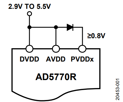
Using a common, positive supply source for the AVDD pin, the DVDD pin, and the PVDDx pins on the AD5770R is the most straightforward way of powering the device. Only a few of the supply conditions required to meet the specified performance of the device require the DVDD pin voltage (DVDD) to equal the AVDD pin voltage (AVDD). The PVDDx pin voltage (PVDDx) must not exceed AVDD − 0.4 V. Given these conditions, the AVDD pin and the DVDD pin can be shorted. To meet the PVDDx ≤ AVDD − 0.4 V requirement, place a diode between the AVDD supply and the PVDDx supply, as shown in Figure 1. In this single-supply configuration, the supply voltage must be in the range of 2.9 V to 5.5 V, and the voltage at the cathode of the diode at the PVDDx pins must be ≥0.8 V.
The main specifications to consider when selecting a diode include the following:
- Forward voltage drop (VF) is ≥0.4 V. Set this specification to ensure that the PVDDx supplies do not exceed AVDD − 0.4 V.
- Forward current rating ≥ the sum of all IDACx currents (IIDACx). Place a derating factor of no more than 80% across all operating temperatures for extra margin.
- Low dynamic resistance. Select the diode with lower dynamic resistance to prevent large PVDDx supply variation with respect to the change in output currents.
Based on these specification considerations, a Diodes, Inc., S1MSWF diode, which has a forward current rating of 1 A, is acceptable for use. The S1MSWF VF value satisfies the requirement, even at very low forward currents and high ambient temperatures. The relationship between IIDACx, VF, and the effect they have on the headroom must also be considered when selecting the supply values and the diode. Increasing IIDACx settings results in an increased VF value, which decreases the available headroom at the output.
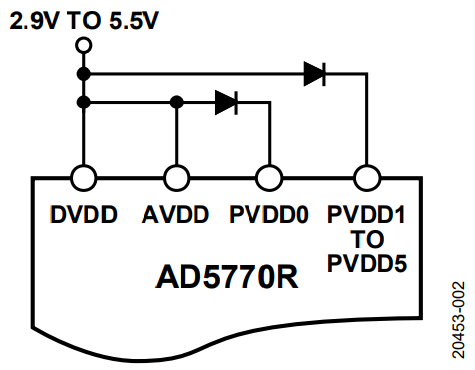
The AD5770R has a dc power supply rejection ratio (PSRR) performance of 17 μA/V to ensure minimal effect of supply change to the output current. To further reduce the effect of crosstalk due to dynamic changes in the load and output currents, isolate the PVDDx pin of those particular channels with a dedicated diode, as shown in Figure 2, depending on the number of diodes required. A Diodes, Inc., BAV23A diode contains two diodes in a single package to save board space, and is acceptable for use. Decoupling capacitors are required in any power supply configuration, and it is recommended to place a 10 μF tantalum capacitor in parallel with a 0.1 μF ceramic capacitor. These capacitors must be located as close as possible to the package to provide a low impedance path to ground for high frequency noise present at the supplies. For unused DAC channels, the PVDDx pins, CDAMP_IDACx pins, and IDACx pins can be left floating.
AD5770R Output Current Ranges with Minimum Headroom and Footroom
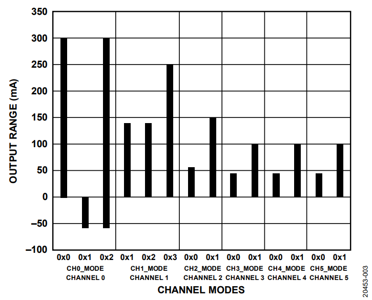
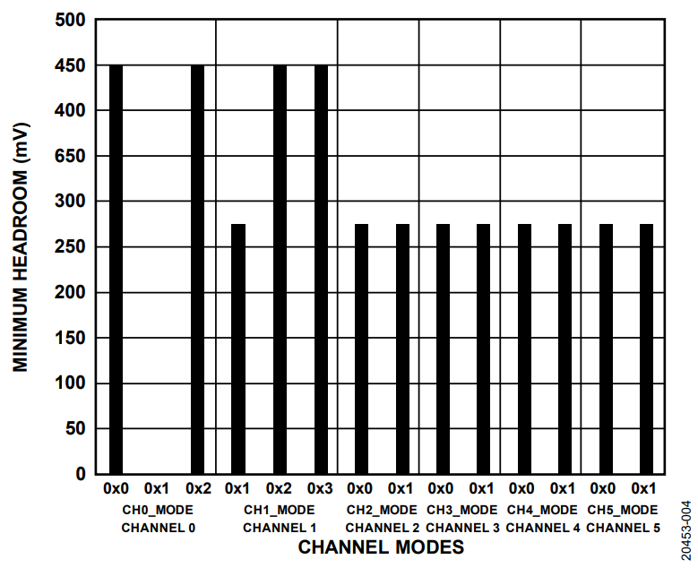
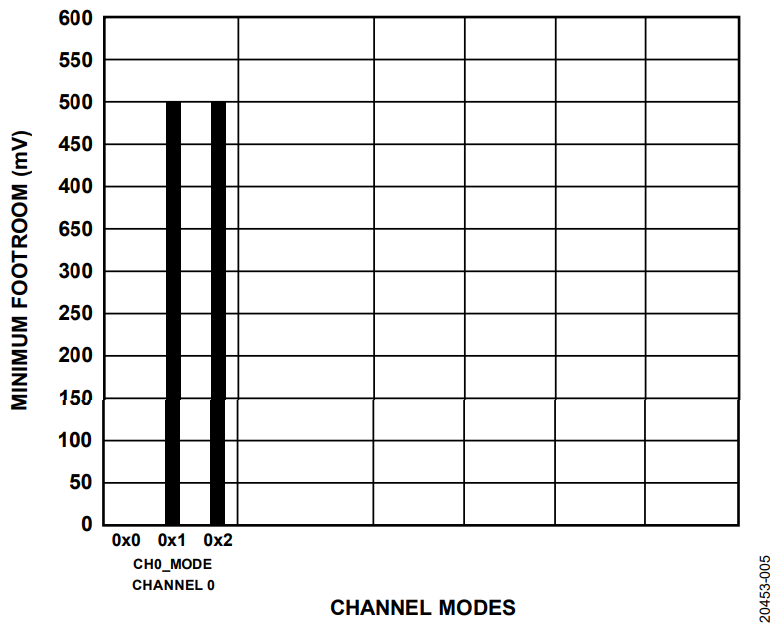
Figure 3, Figure 4, and Figure 5 show the output current ranges available for the different current output channels (IDACx), the minimum headroom, and the minimum footroom, respectively.
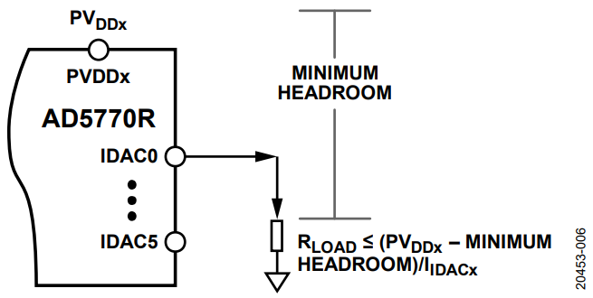
The minimum headroom for the AD5770R is defined as the minimum allowable voltage difference between the PVDDx and the corresponding IDACx pin voltage (VIDACx) with the output current error within 0.1% full-scale range (FSR). This requirement determines the maximum load resistance for a given IIDACx setting. For diode loads, this requirement determines the maximum number of diodes loaded in series while maintaining accuracy. When efficiency is the priority, the compliance voltage can be increased with a small expense in accuracy at high output current settings.
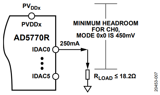
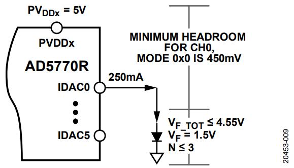
To compute the maximum load resistance, use the equation shown in Figure 6. Using the example shown in Figure 7, when the maximum current to be sourced by the IDAC0 pin is 250 mA, PVDDx = 5 V given that the minimum headroom for the IDAC0 pin, Mode 0x0, is 450 mV. The maximum total load resistance (RLOAD) at the IDAC0 pin must be ≤18.2 Ω.
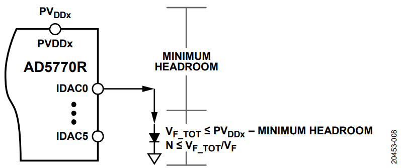
For diode loads, use the equations shown in Figure 8 to determine the total number of identical diodes with similar VF. Using the IDAC0 pin, Mode 0x0, and a PVDDx of 5 V (see Figure 9), the total VF of the diode or diodes in series (VF_TOT) is ≤4.55 V. If each diode has a VF of 1.5 V, no more than three identical diodes can be used as a load. The total number of diodes (N) is not dependent on the current for ideal diodes. Adjustments must be made on the actual VF value depending on the device being used. Note that the actual VF value also varies according to the operating temperature. Most diode manufacturers provide the characteristics for this particular parameter on the device data sheets.
The minimum headroom and footroom depend on the actual output current of a given channel (see the AD5770R data sheet for more information). Applications with large load impedance typically require higher supply voltages. In these cases, the recommended device is the LTC2662, for which the supplies can be up to 33 V.
For a given output current, the minimum headroom increases with temperature because of the positive thermal coefficient of the internal resistance of the output current driver. The increase in resistance results in a higher voltage drop across the driver and leaves a smaller margin between the VIDACx and PVDDx. For example, at 25°C, a headroom of about 270 mV allows the device to source up to 250 mA of output current. With a target load resistance that is ground referenced, the minimum supply voltage can be computed using Equation 1. For the IDAC0 current sink mode, use Equation 2 to solve for the maximum PVEEx pin voltage (PVEEx).


AD5770R Output Current Scaling
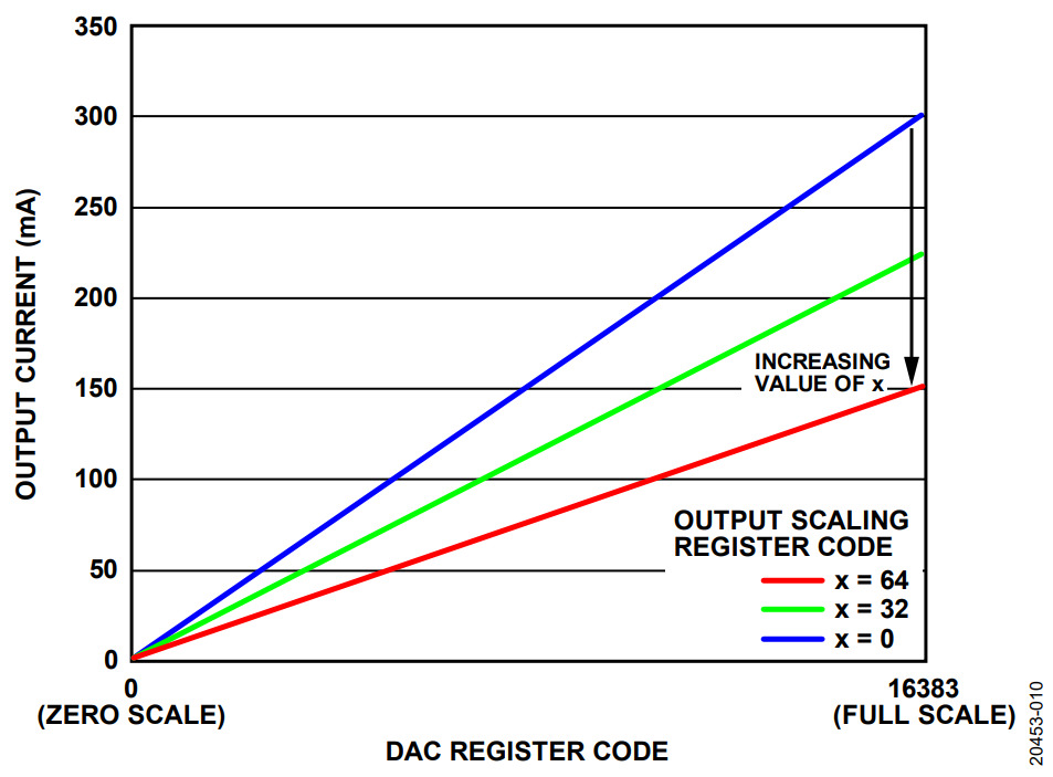
Each output shown in Figure 3 can be scaled down to a minimum of 0.5 times the nominal, full-scale current range while maintaining a 14-bit monotonicity, with the exception of the IDAC0 pin, Mode 0x1 and Mode 0x2, where output current scaling is not supported.
Output current scaling loads the desired value to the output scaling register. The new adjusted, full-scale current range is determined using the following equation:

where:
IADJ is the adjusted full-scale output current.
INOM is the nominal full-scale output current.
x is the code loaded into the output scaling register, 0 ≤ x.
To determine the value of x in Equation 3, use the following equation:

Using the IDAC0 pin, Mode 0x0, as an example with a nominal, full-scale output current of 300 mA, the code required to achieve an adjusted, full-scale output current of 225 mA is x = 32. The code required to achieve the lowest adjusted, full-scale output current of 150 mA (exactly half of the nominal value) is x = 64.
As shown in Figure 10, increasing the value of x results in decreasing the IADJ. The zero scale output current is still 0 mA for all cases.
Thermal Monitoring and Considerations
The AD5770R offers monitoring of the internal die temperature of the device through an output voltage at the MUX_OUT pin as a representative of the temperature. To monitor the internal die temperature, set up the internal multiplexer first and then select the bias current for the internal diode. The internal diode acts as the temperature sensor. When using the external bias current, bypass the multiplexer (MUX) buffer before enabling the bias current source. See the AD5770R data sheet for details on the configuration of the MUX_OUT pin for this functionality. Figure 11 shows the simplified block diagram of the MUX_OUT section with a focus on the internal die temperature monitoring.
There are three options for the bias current: the internal bias current, a 100 μA external bias current, and a 200 μA external bias current. Depending on the bias current used, the equivalent temperature in °C is represented by any of the following equations:

where:
T is the die temperature using the internal bias current.
VD is the diode voltage.

where T is the die temperature using a 100 μA external bias current.

where T is the die temperature using a 200 μA external bias current.
The AD5770R features an overtemperature warning and overtemperature shutdown alert to flag the application system if the internal die temperature exceeds the warning limit (120°C) or the shutdown temperature limit (145°C). The overtemperature alert feature can also be configured to shut down the output current stages to protect the device from overtemperature.
Approximate the internal junction temperature (TJ) of AD5770R using the ambient temperature (TA) given by the following equation:

where:
θJA is the junction to ambient thermal resistance.
PDISS is the power dissipation.
Rearrange Equation 8 to estimate the maximum power dissipation (see Equation 9) or the maximum ambient temperature (see Equation 10). The maximum operating ambient temperature and the power dissipation can be improved by implementing additional copper planes and vias that are directly connected to the device. A heatsink can also be installed on top of the case. Both methods increase the surface area to dissipate heat at a faster rate.


Bipolar Current Supply and Inductive Loads
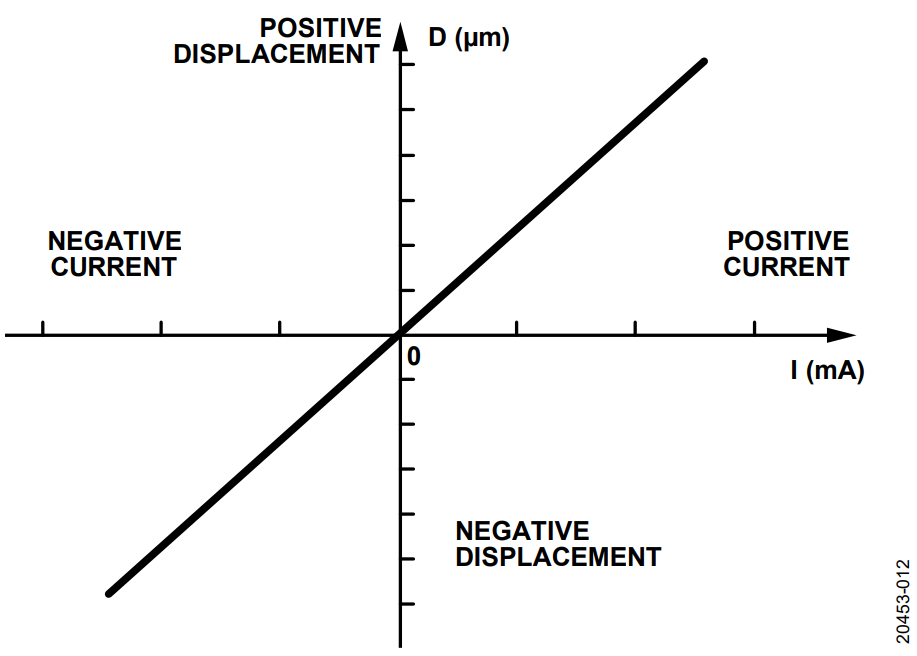
Microelectromechanical system (MEMS) actuators driven by Lorentz force are recommended because they are able to provide large displacements at small voltages (3.3 V or 5 V). The resultant force (displacement) is dependent on the magnetic flux density of the magnetic field, and on the amount of current passing through the movable section. Given a fixed magnetic flux density, the actuator current is adjusted to change the displacement. Figure 12 shows the relationship between the current and the displacement.
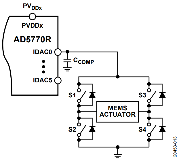
The MEMS actuators require a bipolar drive current to allow the actuators to move in both directions. Only the IDAC0 pin has the capability to source and sink the current. The circuit shown in Figure 13 can be implemented for other channels, which can only source current. This circuit is a classical H-bridge. When the S1 and S4 switches are closed, the S2 and S3 switches are open and the current flows from the left to the right of the MEMS actuator. When the S2 and S3 switches are closed, the S1 and S4 switches are open and the current flows from the right to the left of the MEMS actuator. These two combinations create a bipolar current through the actuator. The inductive nature of MEMS actuators may require a compensating capacitor (CCOMP) at the IDACx pins to ensure output stability. A 22 nF capacitor between the IDACx pins and the AGND pin ensures the stability of a 10 μH load. Note that this capacitive component may also result in a slower settling time for the outputs.
