AN-1580: Synchronizing Multiple AD9910 1 GSPS Direct Digital Synthesizers
Circuit Function and Benefits
Synchronization of multiple direct digital synthesizer (DDS) devices allows precise digital tuning control of the phase and amplitude across multiple frequency carriers, which is useful in radar applications and quadrature (I/Q) upconversion for sideband suppression.
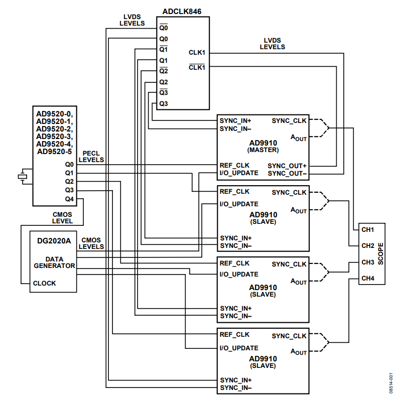
The circuit in Figure 1 demonstrates how to synchronize four AD9910 1 GSPS, DDS chips using the AD9520-0, AD9520-1, AD9520-2, AD9520-3, AD9520-4, or AD9520-5 clock generator and the ADCLK846 clock fanout buffer. The result is precise phase alignment between the clock and output signals of four AD9910 devices.

Circuit Description
The circuit in Figure 1 was constructed by connecting the respecttive evaluation boards for the individual devices. Connections were made with matched cable lengths. The first of three basic requirements to synchronize multiple AD9910 devices is to provide a coincident reference clock (REF_CLK).
The setup uses the AD9520-0, AD9520-1, AD9520-2, AD9520-3, AD9520-4, or AD9520-5 as the REF_CLK source for each AD9910. The AD9520-0, AD9520-1, AD9520-2, AD9520-3, AD9520-4, or AD9520-5 runs off an external crystal and the internal phase-locked loop (PLL). The AD9520-0, AD9520-1, AD9520-2, AD9520-3, AD9520-4, or AD9520-5 distributes phasealigned, 1 GHz REF_CLK signals (positive emitter-coupled logic (PECL) outputs) to all four EVAL-AD9910 evaluation boards. The AD9910 provides a complementary metal-oxide semiconductor (CMOS) output clock to the DG2020A data pattern generator for the I/O_UPDATE signal.
The second step to synchronize the AD9910 devices is to align the rising edge of the SYNC_CLK signals for all four AD9910 devices. The SYNC_CLK signal provides the reference for a coincident I/O_UPDATE signal. SYNC_CLK signal alignment is accomplished with the internal synchronization capability of the AD9910. The ADCLK846 distributes phase-aligned SYNC_IN± signal to all four AD9910 devices. See the AD9910 data sheet for more details.
Figure 2 shows all four SYNC_CLK signals with the AD9910 internal synchronization circuit disabled. Note that the SYNC_CLK signals are not inherently aligned, even when the REF_CLK signals are phase-aligned.
To phase align the rising edges of the SYNC_CLK signals, one AD9910 is programmed as the master device and the other three are programmed as slave devices. The SYNC_OUT± signal of the master device is a low voltage differential signaling (LVDS) signal that is buffered and distributed by the ADCLK846 to the EVAL-AD9910. The SYNC_IN± (LVDS) signal must meet the internal setup and hold time requirements of the system clock of each device. To support this timing requirement, the AD9910 can delay the SYNC_OUT± signal of the master AD9910. For additional flexibility, the internal SYNC_IN± signal path of each AD9910 can be independently delayed.


In the setup shown in Figure 1, the connections between boards were made using matched cables, making it possible to use the internal default delay values to phase-align the SYNC_CLK signals. Figure 3 shows SYNC_CLK signal phase alignment via the using the synchronization procedure.


The last requirement to synchronize multiple DDS devices is a coincident I/O_UPDATE signal, which must match the setup and hold times of the SYNC_CLK signals. The I/O_UPDATE signal, as shown in Figure 1, is sent synchronously to the SYNC_CLK pin, which enables control of the DDS outputs.
Figure 4 and Figure 5 show the DDS outputs in phase alignment. The synchronized devices enable predictable phase and/or amplitude adjustment between DDS devices.


Note that the system clock in Figure 5 was reduced to operation at 100 MHz and the outputs were unfiltered to display each raw DDS output. Figure 5 also illustrates the value of synchronization with each device outputting the same signal.
Common Variations
Analog Devices, Inc., offers a variety of DDS devices, clock distribution chips, and clock buffers to build a DDS-based clock generator. See the Direct Digital Synthesis page and the Clock & Timing page on the Analog Devices website for more information.