USB Power Manager with High Voltage 2A Bat-Track Buck Regulator
Introduction
Personal navigation devices, HDD-based media players, automotive accessories, and other handheld products draw on an array of power sources for recharging their batteries. These sources include USB (nominally 5V), low voltage wall adapters (4.5-5.5V), high voltage wall adapters (12V–24V), FireWire (8V–33V) and automotive batteries (nominally 12V). The large supply of available sources leads to an increasing need for handheld devices that can accept a wide range of multiple input voltages without the need for myriad external power adapters.
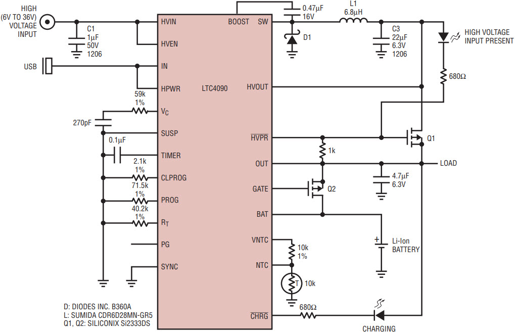
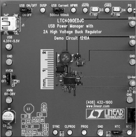
The LTC4090 is designed to accommodate both USB and high voltage sources by integrating a high voltage 2A switching buck regulator, a USB input, a PowerPath™ controller and a linear battery charger into a compact, thermally enhanced 3mm × 6mm package. Figure 1 shows a complete solution that fits into less than 3cm2 with all components on one side of the PCB (Figure 2).

Figure 1. Li-Ion battery charger accepts both USB and high voltage inputs.

Figure 2. A complete LTC4090-based USB Power Manager with a 2A high voltage buck regulator fits into 3cm2.
Complete PowerPath Controller
The LTC4090 is a complete PowerPath controller for battery powered applications. It is designed to receive power from a USB input (or 5V wall adapter), a high voltage source, and a single-cell Li-Ion battery. The PowerPath controller distributes the available power, with the load on the OUT pin taking precedence and any remaining current used to charge the Li-Ion battery. The high voltage input takes priority over the USB input (i.e., if both HVIN and IN are connected to power sources, load current and charge current are provided by the HVIN input). Figure 3 shows a simplified block diagram of the PowerPath operation.

Figure 3. Simplified block diagram of the LTC4090 PowerPath operation.
USB Input Current Limit
Power supplies with limited current capability (such as USB) should be connected to the IN pin, which has a programmable current limit. The input current limit is programmed using a single external resistor, RCLPROG, from the CLPROG pin to ground. In Figure 1, a 2.1kΩ CLPROG resistor has been chosen to program the input current limit to 476mA in high power mode (when the HPWR pin is pulled high) or 95mA in low power mode (when the HPWR pin is pulled low). This ensures that the application complies with the USB specification. The sum of battery charge current and the load current (which takes priority) will not exceed the programmed input current limit.
Ideal Diode from BAT to OUT
An ideal diode function automatically delivers power to the load via the ideal diode circuit between the BAT and OUT pins when the load current exceeds the programmed input current limit or when the battery is the only supply available. Powering the load through the ideal diode instead of connecting the load directly to the battery allows a fully charged battery to remain fully charged until external power is removed. The LTC4090 has a 215mΩ internal ideal diode as well as a controller for an optional external ideal diode. In Figure 1, an external P-channel MOSFET, Q2, is shown from BAT to OUT and serves to further increase the conductance of the ideal diode.
High Voltage Buck Regulator
The LTC4090 has an operating input voltage range of 6V to 36V and can withstand voltage transients of up to 60V. The buck converter output, HVOUT, maintains approximately 300mV across the battery charger from OUT to BAT so that the battery can be efficiently charged with the linear charger. The minimum VHVOUT is 3.6V to ensure the system can operate even if the battery is excessively discharged. As shown in Figure 1, an external PFET, Q1, between HVOUT and OUT is controlled by the HVPR pin and allows OUT to supply power to the load and to charge the battery. The buck converter is capable of up to 2A of output current.
Battery Charger Features
The LTC4090 battery charger uses a unique constant-current, constant-voltage, constant-temperature charge algorithm with programmable charge current up to 1.5A and a final float voltage of 4.2V ±0.8%. The maximum charge current is programmed using a single external resistor, RPROG, from the PROG pin to ground. In Figure 1, a 71.5k PROG resistor programs the maximum charge current to 700mA. However, in the case where only a USB input is present, charge current is reduced to ensure that the programmed input current limit is not exceeded. For the circuit in Figure 1, when only a USB input is present, the actual maximum charge current is reduced to 476mA.
In typical operation, the charge cycle begins in constant-current mode. A strong pull-down on the CHRG pin indicates that the battery is charging. In constant current mode, the charge current is set by RPROG. When the battery approaches the final float voltage of 4.2V, the charge current starts to decrease as the battery charger switches to constant-voltage mode. When the charge current drops to 10% of the full-scale charge current, commonly referred to as the C/10 point, the open-drain charge status pin, CHRG, assumes a high impedance state. An external capacitor on the TIMER pin sets the total minimum charge time. In Figure 1, a 0.1µF capacitor on the TIMER pin gives a 2.145hr minimum charge time. When this time elapses, the charge cycle terminates and the CHRG pin assumes a high impedance state, if it has not already done so.
Charge Time is Automatically Extended
The LTC4090 has a feature that automatically extends charge time if the charge current in constant current mode is reduced during the charging cycle. Reduction can be due to thermal regulation or the need to maintain the programmed input current limit. The charge time is extended inversely proportional to the actual charge current delivered to the battery. The decrease in charge current as the LTC4090 approaches constant-voltage mode is due to normal charging operation and does not affect the timer duration.
Trickle Charge and Defective Battery Detection
At the beginning of a charge cycle, if the battery voltage is below 2.9V, the charger goes into trickle charge reducing the charge current to 10% of the full-scale current. If the low battery voltage persists for one quarter of the programmed total charge time, the battery is assumed to be defective, the charge cycle is terminated and the CHRG pin output assumes a high impedance state. If for any reason the battery voltage rises above ~2.9V the charge cycle is restarted.
Conclusion
The LTC4090 combines a high voltage switching buck regulator, a full-featured Li-Ion battery charger, and a PowerPath controller in a tiny 3mm × 6mm DFN package. Its wide input voltage range, high programmable charge current, and small footprint.


