要約
This article explains the function and basic operation of a hot-swap controller and some of the schemes used to control inrush current. It discusses hot-swap controller features and trends, and gives tips for board layout and choosing MOSFETs.
Hot-swap controller ICs prevent damage and operational faults in applications where a line card needs to be inserted into a live backplane.
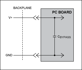
When a line card is plugged into a live backplane, the card's discharged power supply filter capacitors present a low impedance and demand a large, sudden "inrush" current. This sudden high load can cause the backplane's power supply to collapse. See Figure 1a.
Hot-swap controllers, which reside either in the backplane or in the removable card, provide inrush current limiting when the card is first inserted, and short-circuit protection while the card is in operation.

Figure 1a. A PC board plugged into a powered backplane usually draws excessive current and creates a spike on the backplane's power supply. Because the PC board's bypass capacitor is almost always discharged when the board is plugged into the backplane, it draws significant current in this situation.
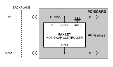
Figure 1b shows how a hot-swap controller limits the inrush current by slowly decreasing the on-resistance of an N-channel MOSFET. When the board is first plugged in, the controller slowly enhances the MOSFET, allowing the voltage at the MOSFET's drain to rise from zero volts (or fall from zero volts for PC boards powered by a negative supply). Two schemes for controlling this rise (or fall) from zero volts are common.

Figure 1b. Adding a hot-swap controller to the PC board limits the inrush current by controlling the slew rate of the voltage applied to the bypass capacitor.
One scheme exploits the fact that the current through a capacitor equals C dV/dt. Controlling the slew rate (i.e., dV/dt) controls the amount of current that flows into the bypass capacitor. While this method is quite easy to implement (it requires that a constant-current source within the IC feed the gate of the MOSFET, and that the value of the MOSFET's gate-to-source capacitance be known), it does come with a drawback: it relies on the value of C, the bypass capacitor. Given that the tolerance of an electrolytic capacitor can range from +20% to -60%, this technique doesn't supply sufficient precision in some cases. The tolerance of the capacitor, along with that of the current source feeding the MOSFET, may make it necessary to bring up the current more slowly than is wanted to ensure that it doesn't become excessive. This method often requires that an additional RC network be connected across the gate and source of the MOSFET. The RC network must be sized appropriately for the bypass capacitor and must be resized when the bypass capacitor changes.
A more accurate method is to control the inrush current directly, by sensing the current across a sense resistor and controlling the gate accordingly. The value of the bypass capacitor doesn't play a part in determining the amount of current that flows through it and the approach isn't sensitive to the MOSFET gate-to-source capacitance, so it doesn't require an external RC network. It does require a much more sophisticated feedback system but the complexities are already incorporated in hot-swap ICs.
Some hot-swap controllers provide the circuitry to allow you to choose either technique for controlling the inrush current.
Features Found Within Hot-Swap Controllers
Hot-swap controllers come equipped with a variety of features. For example, many controllers keep the MOSFET off when certain conditions are present. Two such conditions include a supply voltage that's below the controller's undervoltage lockout level, and die temperature within the controller that's above a specific temperature threshold. The first feature, undervoltage lockout, protects the MOSFET from insufficient gate-drive voltage. The second feature, sensing the controller's die temperature, also protects the MOSFET, but only if the controller is in good thermal contact with it. This feature prevents the MOSFET from operating when its temperature runs too hot.
Once hot-swap controllers have safely connected a board to a live backplane, they in most cases provide short-circuit protection in the event the board draws excessive current from the backplane's power supply. After the MOSFET has opened during a short-circuit or an extended glitch, the controller may latch it in this open state and require that a command be issued to reconnect the supply to the card. Or it may automatically try to reconnect the board to the supply if the initial conditions described in the above paragraph are met.
The current limit on some controllers can be programmed, allowing the MOSFET to open when a line card draws current above a specific level. Also, certain controllers can detect two different types of high-current situations: a large-amplitude, fast event (a short circuit) and a small-amplitude, slow event (a glitch). Here the controller can act quickly to open the MOSFET when it detects a short. But it also can ignore momentary low-amplitude glitches until an extended overcurrent glitch is encountered, at which point it slowly opens the MOSFET.
Other features found within these controllers are also programmable. Some devices allow you vary the slew rate through which the inrush current is controlled during startup. Others allow you to vary the undervoltage lockout level. Yet others allow you to program the overvoltage protection - a feature that detects when the supply voltage has risen above a safe level, turning off the MOSFET when that occurs.
Trends in Hot-Swap Controller Features
The latest controllers have changed the two-level scheme for detecting high-current conditions. A response to a short-circuit can now be made within 260ns. But at the same time, the noise immunity of these circuits has been improved; they can tolerate glitches of up to 3ms duration prior to opening the MOSFET. Also, the glitch duration required to turn off the MOSFET varies in proportion to the level of the glitch; low-amplitude glitches must last 3ms to open the MOSFET, while higher-amplitude glitches need last proportionally shorter durations.
Because hot-swap controllers now monitor voltages as low as 1V, the amount of voltage dropped across the sense resistor has become more important. The accuracy of the voltage of course increases as the voltage dropped across the sense resistor diminishes. A typical controller detects a short-circuit condition with 50mV dropped across the sense resistor. Devices with drops as low as 25mV are currently available.
To reduce component count, some controllers now eliminate the sense resistor. They monitor the drop across the drain and source of the MOSFET, instead of across the current-sense resistor, to determine the amount of current flowing into the line card. Figure 2 shows a controller that uses this technique while monitoring the -48V supply that typically powers a telecom line card.

Figure 2. The current-sense resistor found on most hot-swap controllers can be replaced by monitoring the MOSFET's drain-to-source voltage. The controller shown here uses this technique while monitoring the -48V battery that commonly powers telecom line cards.
Instead of monitoring a single voltage, many hot-swap controllers today monitor two, three, or four voltages at once. Line cards that include a daughter card (whose presence changes the function of the line card) constitute one example of this trend. These hot-swappable daughter cards are often powered by two low-voltage supplies, both of which get monitored by a hot-swap controller; 1.8V and 2.5V supplies are common.
The board area these controllers consume is now more of an issue because the PC boards on which they reside have become more densely populated with components. Also, the controllers' height has become a concern because more and more boards are today housed within the same standard-size rack. Blade servers are a good example: each line card acts as a sort of server, and many of them are required.
Tips on Using Hot-Swap Controllers
The layout of a hot-swap controller is important, as short traces yield quick responses to short circuits and glitches. Also, it's important to maximize the high-current trace dimensions to reduce the effect of parasitic inductance. Two tips for achieving these layout restrictions: place the controller close to the line-card's edge and use a ground plane to minimize impedance and inductance. When a sense resistor is used, its leads should also be of minimum length as well as Kelvin-connected to ensure accurate current sensing.
When the output is short-circuited, the voltage drop across the MOSFET becomes large. Hence, the power dissipation across the switch increases, as does the die temperature. An efficient way to achieve good power dissipation on a surface-mount package is to lay out two copper pads directly under the MOSFET package on both sides of the boards. You can then connect the two pads to the ground plane through vias, and use enlarged copper mounting pads on the top side of the board.
As mentioned above, if the hot-swap controller senses its own die temperature, make sure to mount the MOSFET close to the controller so that the controller can detect excessive MOSFET temperatures.
In most cases, hot-swap controller manufacturers list one or more MOSFETs that work well with a particular controller. When choosing your own MOSFET, select it according to the application's current level. The MOSFET's on-resistance (RDS(ON))should be chosen low enough to have a minimum voltage drop at full load to limit the MOSFET power dissipation. High on-resistance can cause output ripple if the board has pulsing loads or triggers an external undervoltage reset monitor at full load. Choose the MOSFET's power rating based on the worst-case scenario that a particular controller can undergo. Controllers that latch the MOSFET off under a high-current condition can often use MOSFETs with higher on-resistance and lower power ratings, as MOSFETs can typically withstand single-shot pulses with higher dissipation than the specified package rating.


