要約
It takes carefully designed and implemented circuitry to design a high-accuracy thermocouple interface. The first step is to understand the underlying physics principles of this widely used temperature sensor.
Invented in 1921 and approaching their centennial anniversary, thermocouples (TCs) continue to provide valuable temperature measurement information in many applications, especially those that involve very high temperature. Within the multitude of industrial and process critical applications, both TCs and resistor temperature detectors (RTDs) have become the gold standard for temperature measurement. Although RTDs have better accuracy and repeatability, thermocouple advantages include:
- Larger measurement range,
- Shorter response times,
- Lower cost,
- Better durability,
- Self power (no excitation signal required), and
- No self-heating effect.
For these reasons, thermocouples are widely used in many different applications. However, making high accuracy temperature measurements with thermocouples can be tricky. This application note discusses ways to optimize measurement accuracy. First, let's describe the fundamentals of thermocouple operation.
How Do Thermocouples Work?
When a voltage source is applied across a piece of metal wire, electrons flow from positive terminal to negative terminal, and some energy is lost heating up the metal wire. The Seebeck effect, discovered in 1821 by Thomas Johann Seebeck, indicates a reverse phenomenon. When a temperature gradient is applied across a metal wire, an electric potential is created. This is the physical basis of a thermocouple.
| ?V = S(T) × ?T | (Eq. 1) |
Where, ?V is the gradient of voltage, ?T is the gradient of temperature, and S(T) is the Seebeck coefficient. The Seebeck coefficient is material dependent, and it also varies as a function of temperature. The voltage across two different temperature points on a wire equals the integration of the Seebeck coefficient function over the temperature range.
 | (Eq. 2) |
For example, Figure 1 shows a piece of metal wire in black. T1, T2, and T3 represent the temperatures at different locations on the wire. T1 in blue is the coldest point and T3 is the hottest point. The voltage across point T2 and T1 is  . Similarly the voltage across point T3 and point T1 is
  . V31 also equals
  because of the additive property of definite integral. Keep this in mind, as this application note further explains the thermocouple voltage to temperature conversion.
 Figure 1. Voltage created on a conductive wire by temperature gradient.
Thermocouples consist of two dissimilar materials, usually metal wires with different Seebeck coefficient functions, S(T). Why are two materials essential when a temperature difference in a single material produces a voltage difference? For example, assume the metal wire in Figure 2 is made of material A. Given a voltmeter with probe wires, also made of material A, theoretically the voltmeter will not detect any voltage. Why? When the probes are connected to the ends of the wire, the probes act like the extension of the metal wire. The ends of this long wire that connect to the inputs of the voltmeter are at the same temperature (TM). If the ends of a wire are at the same temperature, the temperature difference along the length of the wire does not result in a voltage difference. To prove this mathematically, we calculate the voltage accumulated across the whole wire loop starting from the positive terminal of the voltmeter to the negative terminal.
 | (Eq. 3) |
Using the additive property of integral, the above equation becomes:
 | (Eq. 4) |
And, when the lower bound and upper bound of the integral limits are the same, the result of the integral is V = 0.
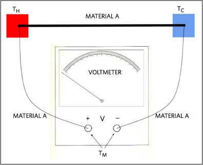 Figure 2. Voltage measurement connection. Probes and wires are made of same material.
If the probe material is made of material B as shown in Figure 3.
 | (Eq. 5) |
Simplifying the integral, we get
 | (Eq. 6) |
The above equation shows the measuring voltage equal to the integral of the difference of the two material type Seebeck coefficient functions. This is the reason why thermocouples are made with two dissimilar types of metal.
 Figure 3. Voltage measurement connection. Probes and wires are made of different materials.
From the circuit shown in Figure 3 and Equation 6 (Eq.6), assuming SA(T), SB(T), and the voltage measured by the voltmeter are known, we still cannot calculate the temperature at the TH junction (hot junction) unless the temperature at TC junction (cold junction) is known. In the early days of thermocouples, an ice bath, corresponding to 0°C, was used as a reference temperature (hence the term cold junction) because this method is low cost, very easily accessible, and temperature self-regulated. An equivalent circuit is shown in Figure 4.
 Figure 4. Figure 3 equivalent circuit with cold junction placed inside an ice bath.
Although we know the reference temperature for the circuit in Figure 3, solving the integral equation for the hot junction temperature (TH) is not practical. Standard reference tables are available for all common types of thermocouples, so users can look up the temperature for corresponding voltage output. But keep in mind, all of the standard thermocouple reference tables were tabulated with 0°C reference temperature.
Modern Day Thermocouple System
A modern thermocouple, as shown in Figure 5, consists of two dissimilar metal wires joined at one end. Voltage is measured at the open ends of the wire pair. An equivalent circuit is shown in Figure 5. VOUT is exactly the same as the equation we derived previously for Figure 3.
 | (Eq. 7) |
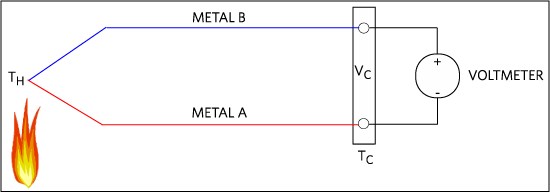 Figure 5. A modern thermocouple configuration.
Cold Junction Compensation
The cold junction (TC) temperature can be set to 0°C with an ice bath, but practically no one would use a bucket of ice water in any modern electrical system. A cold junction compensation method can be used to calculate the hot junction temperature without the need of a 0°C cold junction temperature, and indeed the cold junction temperature does not even have to be constant. This method simply uses a separate temperature sensor to measure the temperature at the cold junction (TC). Finding the hot junction temperature (TH) becomes possible when TC is known. This might sound absurd to some people. If we have a temperature sensor to measure the cold junction temperature, why can't we use this temperature sensor to measure the temperature at the hot junction, directly? The answer is simple. The cold junction temperature range is much narrower than the hot junction temperature, so the temperature sensor does not need to sustain the extreme temperature as the thermocouple does.
Calculating Hot Junction Temperature with Cold Junction Compensation
As mentioned above, all the standard thermocouple reference tables were generated with cold junction held at 0°C. How then, do we use the tables to find the hot junction temperature in this case?
Imagine if the open ends of the above thermocouple got extended as shown in Figure 6. And, the imaginary ends are connected to a junction with 0°C temperature. If we can calculate the value of V0, we can easily find the corresponding hot junction temperature using the reference table.
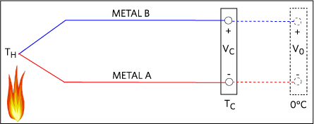 Figure 6. A thermocouple with imaginary extension connected to a 0°C junction.
Let's determine V0:
 | (Eq. 8) |
 | (Eq. 9) |
 | (Eq. 10) |
 | (Eq. 11) |
The first term of equation 10 (Eq.10) is exactly the same as equation 7 (Eq.7), which is derived from Figure 5. So, the equivalent voltage output is VC, and this is a known value since the voltage at the cold junction is being measured by the voltmeter. The second term is equivalent to the voltage output of a thermocouple with a hot junction temperature equal to the TC and cold junction temperature equal to 0°C. Since TC is also being measured by a separate temperature sensor we can use the standard reference table to find the corresponding Seebeck voltage (Vi) for the second term of equation 10 (Eq.10).
| V0 = VC + Vi | (Eq. 12) |
Now that we know the value of V0, the corresponding hot junction temperature (TH) can be determined with the standard reference table.
The steps below summarize the procedure of finding the hot junction temperature with cold junction compensation.
- Measure the cold junction temperature (TC) with a temperature sensor.
- Measure the voltage at the cold junction.
- Convert TC to voltage (Vi) using the standard reference table.
- Calculate V0=Vi+VC.
- Convert V0 to the hot junction temperature (TH) using the standard reference table.
The standard thermocouple reference tables can be found on the NIST ITS-90 thermocouple database website http://srdata.nist.gov/its90/menu/menu.html (by United States Department of Commerce, National Institutes of Standards & Technology). If implementing a look-up table in a microcontroller is not preferable due to lack of memory or any other reasons, the NIST ITS-90 website also provides sets of formulas for each thermocouple type to convert temperature to voltage, and vice versa.
System Design Essentials to Optimize Thermocouple Measurement Accuracy
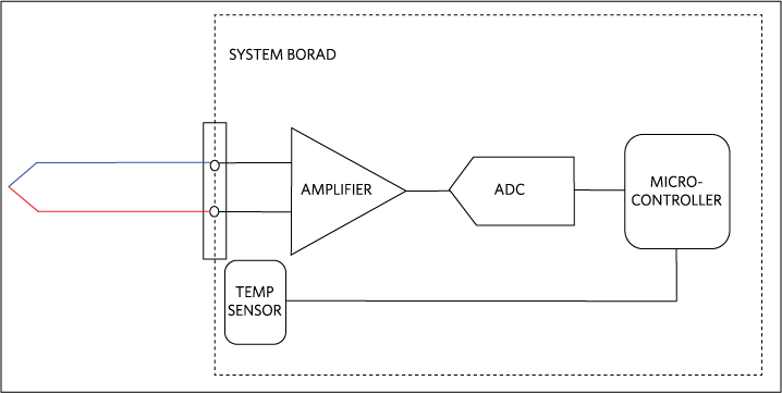 Figure 7. Basic thermocouple system block diagram
So far this discussion has only considered the theory of thermocouples; however, to optimize the accuracy in the real system, a few items should be considered. Figure 7 shows the basic blocks of a thermocouple signal chain. Each device affects the accuracy of the conversion and must be carefully selected to minimize error.
Starting from the left side of the figure, a thermocouple is connected to the system board connector. Although the thermocouple is the sensor itself, it can be the source of error as well. A long thermocouple easily picks up surrounding electromagnetic noise. Shielding the wire can effectively reduce the noise.
The next component is the amplifier. Choosing an amplifier with high input impedance is important, because the input impedance of the amplifier and the thermocouple resistance produce the voltage divider effect as shown in equation 13 (Eq.13). The higher the input impedance, the fewer the errors.
 | (Eq. 13) |
Furthermore, the amplifier boosts the thermocouple output, which is usually in the millivolt range. While the high closed-loop gain amplifies both the signal and the noise, the addition of a low-pass filter at the ADC input eliminates most of the noise. A low pass filter is effective because the ADC conversion rates for temperature measurement applications are usually very slow, perhaps a few samples per second, because temperature does not change very quickly.
Finally, the on-board temperature sensor needs to be located very close to the cold junction connector (ideally touching the ends of the thermocouple leads but that is not possible in many cases) to get the best measurement of the cold junction temperature. Any error in the cold junction measurement reflects on the hot junction temperature calculation.
Thermocouple Example Circuit
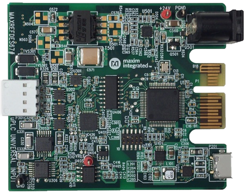 More detailed image.
Figure 8. A universal-input reference design that can measure voltage, current, and voltage with RTD or thermocouple.
The MAXREFDES67# universal-input reference design (Figure 8) contains all the necessary components to implement the thermocouple temperature measurement system. The preloaded firmware uses the formula from the NIST ITS-90 website to convert K-type thermocouple output to temperature. Measurement temperature range from -40°C to +150°C. In addition, this system is also capable of measuring voltage, current, and temperature and RTD with high accuracy.
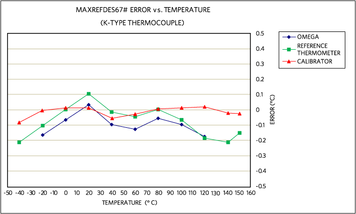 Figure 9. MAXREFDES67# error vs. temperature, using an Omnitec EC3TC, K-type thermocouple calibrated at 20°C.
Figure 9 shows the temperature error measured by the MAXREFDES67# thermocouple input versus temperature referenced to three different reference thermometers, the Omega HH41 thermometer, the ETI reference thermometer, and the Fluke 724 temperature calibrator, respectively. The MAXREFDES67# connected K-type thermocouple probe was placed in the Fluke 7341 calibration bath and calibrated at 20°C. The blue data used the Omega HH41 thermometer as a reference. The green data used the ETI reference thermometer as a reference. The red data used the Fluke 724 temperature calibrator as the reference. This design displays world class thermocouple temperature measurement.
Conclusion
Using thermocouples for industrial temperature measurement applications has many benefits including temperature range, response time, cost and durability. A high-accuracy measurement system can be achieved with the design recommendations outlined here. The MAXREFDES67# is a great example that helps system designers develop high-accuracy thermocouple temperature measurement faster than ever before.


