Applications in the rapidly expanding PoE (power-over-Ethernet) industry now demand power levels higher than the 12.95W supported by the current IEEE 802.3af standard. Accordingly, in September 2005 the IEEE began creating a new standard (IEEE 802.3at) that will extend the power delivered through Ethernet cables to at least 30W. Expected to be finalized in the second quarter of 2008, the new PoE Plus (PoE+) standard will approximately double the power available to PDs (powered devices).

Figure 1. This "pre-PoE+" power circuit delivers 30W at 3.3V. To do so, it simply adds an external MOSFET to the MAX5941B PoE controller
PoE+ Requirements
Some goals of the proposed IEEE 802.3at¹ standard for PoE+ are as follows:
- An IEEE 802.3at system must follow the power safety rules and limitations pertinent to 802.3af
- 802.3at PSEs (power-sourcing equipment) must be backward compatible with 802.3af: they must be capable of powering both 802.3af and 802.3at PDs
- 802.3at PSEs will provide, within practical limits, the maximum allowed power to PDs (at least 30W)
- 802.3at PDs, when connected to a legacy 802.3af PSE, will indicate to the user that an 802.3at PSE is required
Thus, an 802.3at PD must be recognized, detected, and powered by an 802.3at PSE, and should also provide enough power for its downstream load. To adapt to the new 802.3at power requirement, an existing PD controller faces the following issues and problems:
- Class 4 PD classification
- The PD interface isolation switch internal to these controllers is unable to handle power levels higher than the designed maximum of 12.95W
- The current limit set by many existing PD controllers is lower than that necessary for the new 802.3at power level
Fortunately, the MAX5941B controller can provide up to 70W to a pre-PoE+ PD with only a few changes in the external components. Intended for PDs in a PoE system, it integrates a complete 802.3af-compliant power IC with a PD interface and a compact DC-DC PWM controller suitable for flyback or forward converters in either isolated or nonisolated designs.²
A Simple, Cost-Effective Pre-PoE+ Solution
MAX5941B controllers address the PoE+ requirements as follows:
- Class 4 PD classification: The controller already includes provision for a Class 4 PD classification. You need only change the value of the external class-setting resistor.
- Power rating of the PD interface isolation switch: All existing PD controllers include a MOSFET that isolates the PD during the startup protocol of detection and classification. Because this MOSFET was designed for 802.3af power levels (up to 12.95W), it is undersized for 802.3at applications.
- However, the gate of the MOSFET internal to the MAX5941B is accessible on pin 7. You can, therefore, increase the power rating of the PD interface switch by simply connecting an external MOSFET to this gate pin. The new power rating is scalable from 12.95W to 70W and above, depending on the size you select for the external MOSFET. RDS(ON) for the external MOSFET must ensure that current through the internal switch is within its safe operating area.
- Changing the current limit: Many existing PD controllers provide two current-limit levels. The first is set below 400mA to limit the PD inrush current during power-up, and the second is set higher than 400mA. Not only is the second level not required by the 802.3af standard, it actually inhibits the use of these PD controllers in PoE+ applications.
- MAX5941B controllers allow users to program the inrush current while not imposing a second current limit. This proven technique, in which the user can choose an inrush-current limit < 400mA, makes the controller readily adaptable to PoE+ applications. After the inrush period is over, the PD is ready for higher-power PoE+ operation without changing the IC or the external circuitry.
- The bottleneck that limits power transmission in a PoE+ system is the cable's current-carrying capability. Under related standards such as TR42.7,³ numerous tests on PoE+ cables have been conducted to determine their current-carrying capability vs. complex restrictions. Currently, TR42.7 recommends 720mA maximum current per pair (360mA per conductor), and up to 45°C maximum ambient temperature for Cat 5e, 6, and 6A cables. Beyond 45°C, you should derate to 0mA at 60°C as a function of I², where I is the current through the cables. So, for a 2-pair PoE+ system, the maximum power allowed for the PD is approximately 30W. Accordingly, we now propose a 30W power-supply circuit for pre-PoE+ PDs.
PD Interface
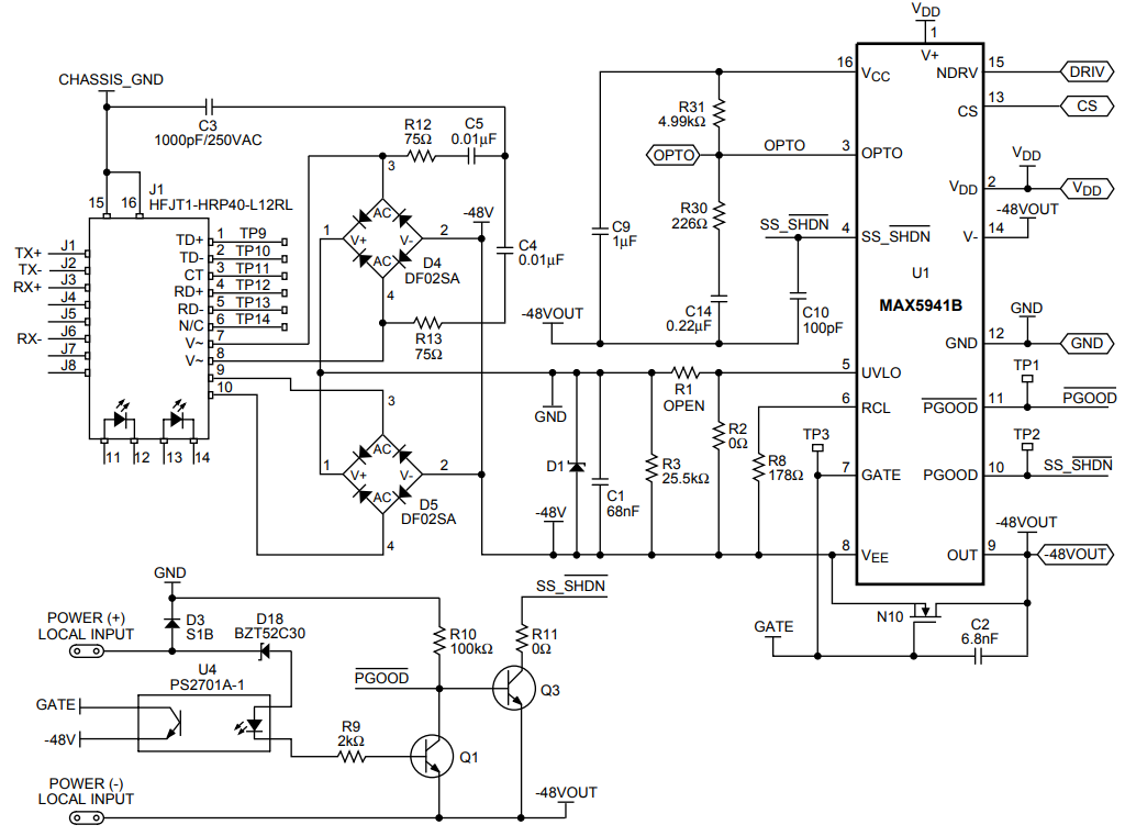
Figure 2. Schematic of the 30W PD interface
Figure 2 provides a schematic of the 30W PD. N10 is the external MOSFET added to enhance the PD interface isolation switch to the PoE+ power level, and R8 (178Ω) is the RCL chosen to set the classification mode to Class 4. This 30W PD can receive power from a pre-802.3at PSE. Two pairs of UTP cables are connected to FastJack™ connector J1, in which a 10/100 Base-TX VoIP magnetic module is integrated. Two diode-bridge power rectifiers (D4, D5) are used to separate the -48V DC power sent by the PSE.
The isolation switch (consisting of a power MOSFET internal to the MAX5941B and the external MOSFET N10) limits inrush current during start-up. The MAX5941B charges the MOSFET gates with a constant-current source of 10µA (typ), and the MOSFET's drain-to-gate capacitance limits inrush current by limiting the rate of voltage rise at the drain. You can further reduce inrush current by adding an external capacitor between the GATE and OUT pins. Use the following equation to calculate the resulting inrush current:

The inrush-current limit for a PoE+ application is 400mA (max). The waveforms in Figure 3 (taken from the Figure 2 circuit) show that inrush current is below 108mA when the input voltage is about 39V, which is the default level for undervoltage lockout (UVLO). When load current is 7A, the overall average current flowing through the isolation switches is 680mA.
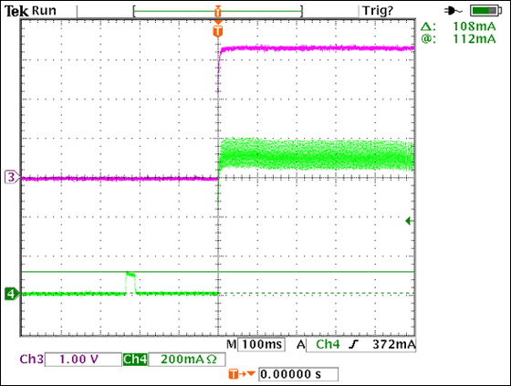
Figure 3. Inrush-current limit for the pre-PoE+ PD
- Ch3: 3.3V output, 1VDC/div
- Ch4: Input current, 200mA/div
- Time base: 100ms/div
3.3V, 30W DC-DC Converter
A schematic of the DC-DC converter for the 30W PD is shown in Figure 4. For power conversion in the PoE power range, the two prime candidates are flyback and forward converters. A flyback converter offers the lowest part count and cost, but it has higher peak currents. Flyback converters, therefore, require a larger output capacitor and/or secondary filter to reduce the output-voltage ripple.
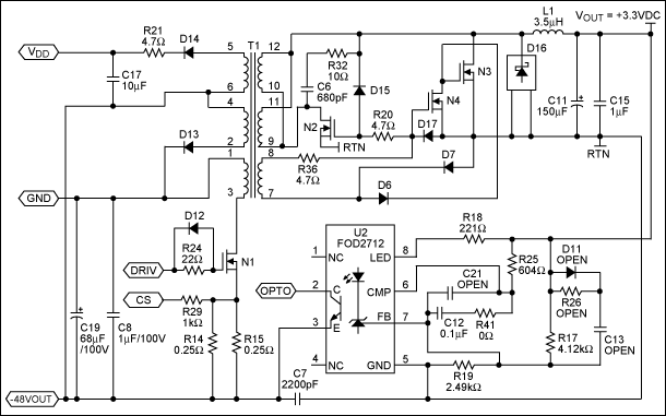
Figure 4. Schematic of the DC-DC converter stage for the 30W PoE+ PD
For a single-output, high-current converter, a single-ended forward converter with synchronous rectification is the best candidate for PoE applications. Its efficient, low-EMI, yet low-cost topology was therefore chosen for this design. Because the fundamentals of a forward converter with synchronous rectification are elaborated in the datasheet for the MAX5941B Evaluation Kit, they will not be discussed here.
Experiment Results
Comprehensive tests were conducted to evaluate the performance of the DC-DC converter. Figure 5 shows a graph of efficiency versus output current, measured with a line voltage of 48V. Power loss in the two diode-bridge power rectifiers (D4, D5) is excluded. (If included, the efficiency drops by approximately 5%.)
Figure 6 illustrates the output ripple for the Figure 4 PD measured under worst-case conditions: 57V input line and 9A load. The result (about 50mV) generally meets the requirement of PoE+ applications, such as 802.11n access points, high-power VoIP video phones, and security cameras. For lower output ripple, you can add a low-ESR ceramic capacitor. A Bode plot for this converter (Figure 7) indicates a phase margin of 45° and a gain margin of 10dB, which imply a good response capability.
For certain applications, you need only the front stage of the PD interface (Figure 2) to operate with an existing DC-DC converter. For that purpose, the base device in Maxim's PD controller family (MAX5940B) can be combined with an external MOSFET and (for example) a MAX15000 DC-DC controller.
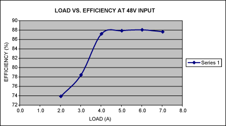
Figure 5. Efficiency vs. output current for the pre-PoE+ PD
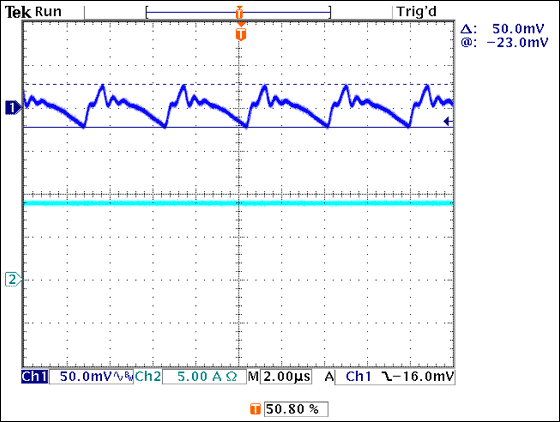
Figure 6. Output ripple for the pre-PoE+ PD
- Ch1: 3.3V output, 50mVAC/div
- Ch2: Load current at 3.3V, 5A/div
- Time base: 2µs/div
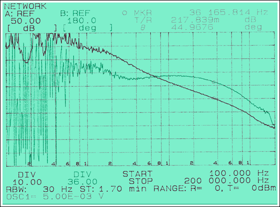
Figure 7. Bode plot of DC-DC converter at maximum input voltage and output current
Summary
Until IEEE standard 802.3at is released, the proposed PD circuit (Figure 2) is a quick, cost-effective, and flexible solution to the problem of powering PoE+ applications. It meets the current requirements of that standard (draft 0.9),4 while maintaining backward compatibility with the current IEEE standard 802.3af. A forward DC-DC converter with synchronous rectification provides high efficiency, low EMI, and low cost. Given enough current capability in the cables connecting the PSE and PD, a MAX5941B controller in that circuit lets you easily upgrade the PD to 70W and beyond.
References
- Approved objectives for IEEE standard P802.3at, Jul 21 05
- IEEE 802.3at-compliant, power-over-Ethernet interface/PWM controller for powered devices, MAX5941A/MAX5941B
- Analysis of current-carrying capacity, TR42.7 update to IEEE standard 802.3at
- IEEE standard 802.3at, draft 0.9 (private)
- This application note is based on an article that appeared in the October 2007 issue of Power Electronics Technology Magazine, a Penton Publication.
While waiting for IEEE 802.3at to be ratified, however, the industry needs "pre-PoE+" circuitry to meet the demands of current applications. This article presents a simple PD operating at a PoE+ power level (30W), with the aid of an external MOSFET and a controller designed for the older 802.3af standard.
The circuit in Figure 1 utilizes the MAX5941B PoE controller to implement a power supply for pre-PoE+ PDs. It satisfies the requirement of many PoE+ applications for higher power, while remaining backward compatible with the 802.3af standard. By simply adding an external MOSFET, the available PD interface power is increased from 802.3af levels to 70W, beyond the proposed maximum power for an 802.3at PD.


