Monolithic Synchronous Step-Down Regulator Drives 8A Loads with Few External Components
Monolithic Synchronous Step-Down Regulator Drives 8A Loads with Few External Components
著者
Joey Esteves
2005年05月01日
Introduction
The LTC3418 is a monolithic synchronous, step-down switching regulator that is capable of delivering 8A of output current for microprocessor and I/O supplies, point of load regulation, and automotive applications. Internal power MOSFET switches, with only 35mΩ on-resistance, allow the LTC3418 to reduce component count while achieving high efficiency. Operating at switching frequencies as high as 4MHz conserves additional space by permitting the use of smaller inductors and capacitors. The LTC3418’s ability to track another voltage supply also allows it to be used in dual-supply systems that require power supply sequencing during start-up.
The LTC3418 employs a constant frequency, current-mode architecture that operates from an input voltage range of 2.25V to 5.5V and provides an adjustable output voltage from 0.8V to 5V while delivering up to 8A of output current. The switching frequency can be set between 300kHz and 4MHz by an external resistor. The LTC3418 can also be synchronized to an external clock, where each switching cycle begins at the falling edge of the external clock signal. Since output voltage ripple is inversely proportional to the switching frequency and the inductor value, a designer can take advantage of the LTC3418’s high switching frequency to use smaller inductors without compromising the output voltage ripple. Lower inductor values translate directly to smaller case sizes, reducing the overall size of the system. OPTI-LOOP® compensation allows the transient response to be optimized over a wide range of loads and output capacitors, including ceramics. For increased thermal handling, the LTC3418 is offered in a 5mm × 8mm QFN package with an exposed pad to facilitate heat sinking.
The LTC3418 can be configured for either Burst Mode, pulse skip or forced continuous operation. Burst Mode operation provides high efficiency over the entire load range by reducing gate charge losses at light loads. In the LTC3418, the burst clamp is adjusted by varying the DC voltage at the Sync/Mode pin within a 0V–1V range. The voltage at this pin sets the minimum peak inductor current during each switching cycle in Burst Mode operation. If the minimum peak inductor current delivers more energy than is demanded by the load current, the internal power switches skip switching cycles to maintain regulation. Burst Mode operation provides an efficient solution for light-load applications, but sometimes noise suppression takes priority over efficiency. Forced continuous operation, though not as efficient as Burst Mode operation at light loads, maintains a steady frequency, making it easier to reduce noise and RF interference.
Voltage tracking is enabled by applying a ramp voltage to the TRACK pin. When the voltage on the TRACK pin is below 0.8V, the feedback voltage regulates to this tracking voltage. When the tracking voltage exceeds 0.8V, tracking is disabled and the feedback voltage regulates to the internal 0.8V reference voltage.
A High Efficiency 1.2V/8A Step-Down Regulator with All Ceramic Capacitors
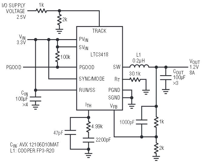
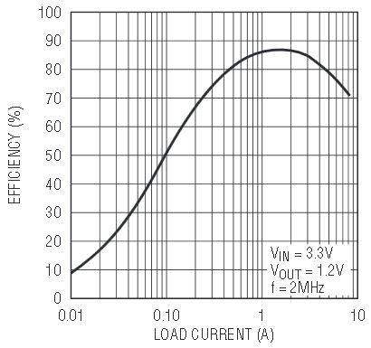
Figure 1 shows a 1.2V step-down switching regulator that can be used as a core supply voltage for microprocessors. It uses all ceramic capacitors and tracks an I/O voltage of 2.5V. This circuit provides a regulated 1.2V output at up to 8A from a 3.3V input. Efficiency for this circuit is as high as 87% and is shown in Figure 2. The switching frequency for this circuit is set at 2MHz by an external resistor, ROSC. Operating at a frequency this high allows the use of a lower valued and physically smaller inductor. During start-up, the output of the LTC3418 coincidentally tracks the I/O supply voltage. Once the I/O supply voltage exceeds 1.2V, tracking is disabled and the LTC3418 regulates its output voltage to 1.2V.

Figure 1. A 1.2V, 8A step-down regulator running at 2MHz, which allows the use of tiny capacitors and inductors. This particular configuration operates at a single frequency in forced continuous mode, which simplifies EMI filtering.

Figure 2. Efficiency vs Load Current.
Ceramic capacitors offer low cost and low ESR, but many switching regulators have difficulty operating with them. The LTC3418, however, includes OPTI-LOOP compensation, which allows it to operate properly with ceramic input and output capacitors. The problem that many switching regulators have when using ceramic capacitors is that their ESR is too low, which leads to loop instability. That is, the phase margin of the control loop can drop to inadequate levels without the aid of the zero that is normally generated from the higher ESR of tantalum capacitors. The LTC3418 allows loop stability to be achieved over a wide range of loads and output capacitors with the proper selection of compensation components at the ITH and VFB pins.
Conclusion
The LTC3418 is a monolithic, synchronous step-down DC/DC converter that is well suited to applications requiring up to 8A of output current. Its high switching frequency and internal low RDS(ON) power switches allow the LTC3418 to provide a small solution size with high efficiency.


