Dragonfly 28 GHz Phased Array Antenna RF Module

Dragonfly 28 GHz Phased Array Antenna RF Module
著者
高松 創
2026年10月13日
A scalable RF front end for over-the-air communication, sensing, and ISAC research
1. Introduction
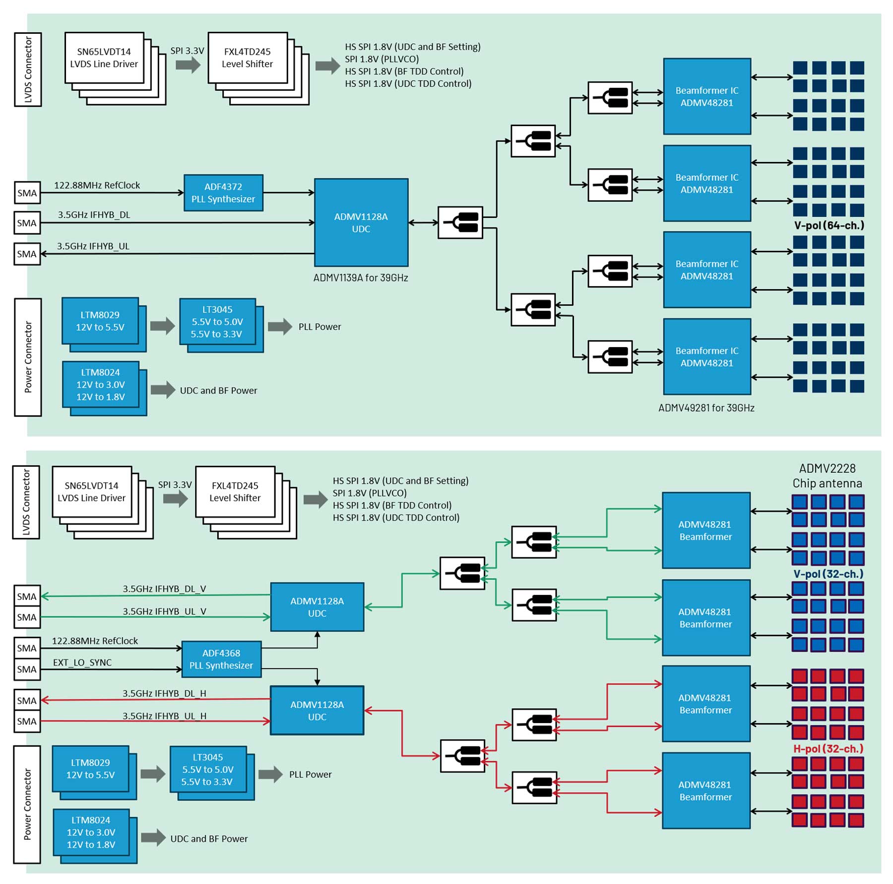
Dragonfly is a 28 GHz phased-array antenna module (PAAM) that integrates the antenna array, beamformer ICs, up/downconverter, PLL/VCO, and low-noise power supplies into a compact RF front end. Developed by Analog Devices K.K. together with Japanese design and manufacturing partners, Dragonfly provides electronically controlled beam steering, frequency conversion, and a transparent 3.5 GHz IF interface for FR2 communication and sensing experiments.
A MATLAB-based development environment provides a common workflow for RF control, calibration, automated characterization, beam management, waveform generation, signal processing, and visualization. Unlike simulation-only environments, Dragonfly enables users to develop, validate, and demonstrate algorithms using real RF signals and physical phased-array hardware.
Dragonfly is designed as a scalable RF front end for Antenna-to-Bit research platforms. By combining Dragonfly with SDRs, wireless-infrastructure transceivers, and FPGA platforms, users can construct complete communication, sensing, and ISAC systems while retaining the same 28 GHz phased-array RF hardware.
2. Project Objective and Key Features
The Dragonfly project bridges the gap between individual RF IC evaluation and complete over-the-air system experimentation. It integrates the following key Analog Devices RF components:
- ADMV48281 millimeter-wave beamformer
- ADMV1128A up/downconverter
- ADF4372 or ADF4368 PLL/VCO
- ADMV2228 chip antenna for Dragonfly DP
- LTM802x and LT3045 ow-noise power-management
Dragonfly enables beam-steering evaluation using real RF signals, supports system-level phased-array validation, and provides low-level access to RF and beam-control functions for communication, sensing, and ISAC research. It also supports customization and commercialization through available reference-design data and manufacturing support.
3. Hardware Overview
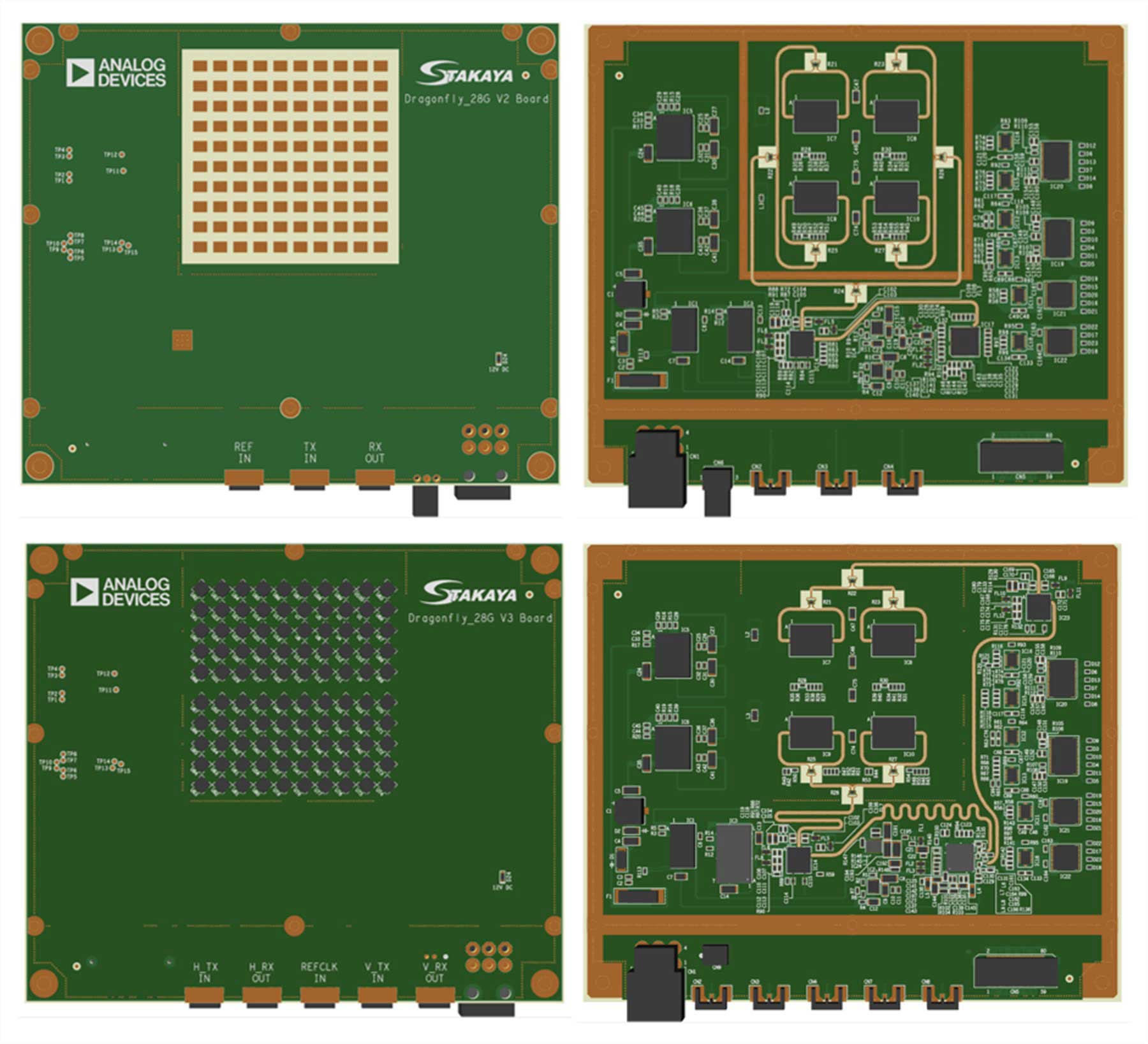
Dragonfly is available in two variants. Dragonfly SP uses a 64-element single-polarization patch array optimized for 27.8 GHz to 29.1 GHz. Dragonfly DP uses 32 H-polarized and 32 V-polarized antenna elements with dual IF paths and supports 24.0 GHz to 29.5 GHz operation. Both variants use a common 3.5 GHz IF and software framework.
| Item | Dragonfly SP | Dragonfly DP |
| Number of elements | 64 (8 x 8) | 64 total (32 H + 32 V) |
| Polarization | Single (V) | Dual (H/V) |
| RF frequency | 27.8-29.1 GHz | 24.0-29.5 GHz |
| IF streams | One TX/RX pair | Two TX/RX pairs |
| IF frequency / bandwidth | 3.5 GHz / 400 MHz | 3.5 GHz / 400 MHz |
| Reference clock | 122.88 MHz | 122.88 MHz |
| Beam angle | ±45° | ±45° |
4. Dragonfly SDK
Practical operation requires beam-control interfaces, IF signal generation and acquisition, and a reference-clock source. Dragonfly SDK solutions integrate control electronics, enclosure hardware, cooling, and MATLAB-compatible software to simplify evaluation and prototyping.
| Item | model-I | model-S |
| Control interface | USB-C | RJ-45 LAN (GbE/UDP) |
| Interface bridge | FTDI4232HL | Digilent Zybo Z7 |
| Reference clock | External 122.88 MHz | Onboard 122.88 MHz output |
| Auxiliary control | 20-pin port | - |
| Primary positioning | Integration/customization | Standard evaluation/supply |
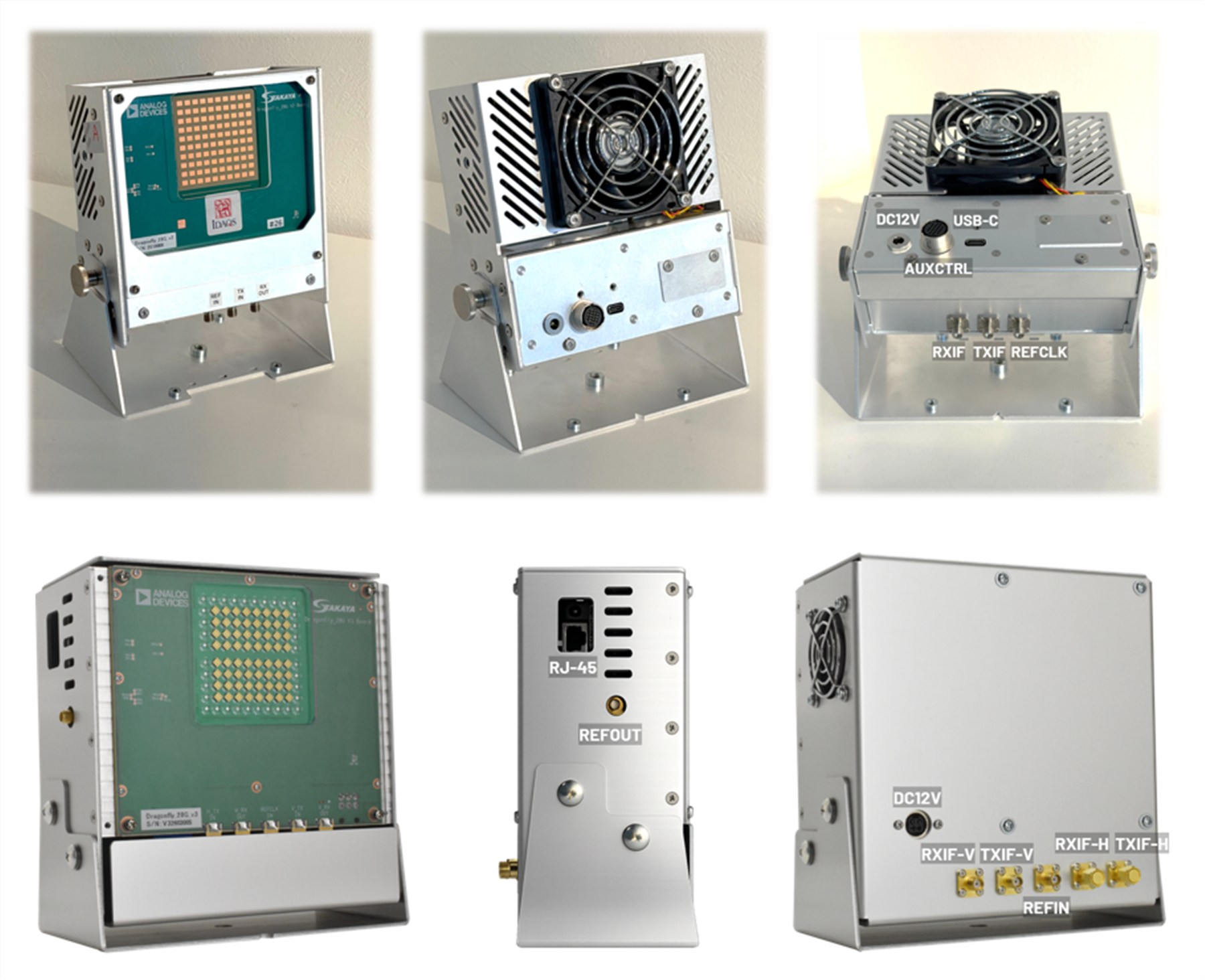
Two Dragonfly SDK variants are available and both support Dragonfly SP, Dragonfly DP, SPI streaming, and a common MATLAB API. Model-S, supplied by S-Takaya, is optimized for standard LAN-based evaluation and product deployment. Model-I, supplied by IDAQS, provides additional flexibility through USB connectivity and an auxiliary control interface for system integration and customization.
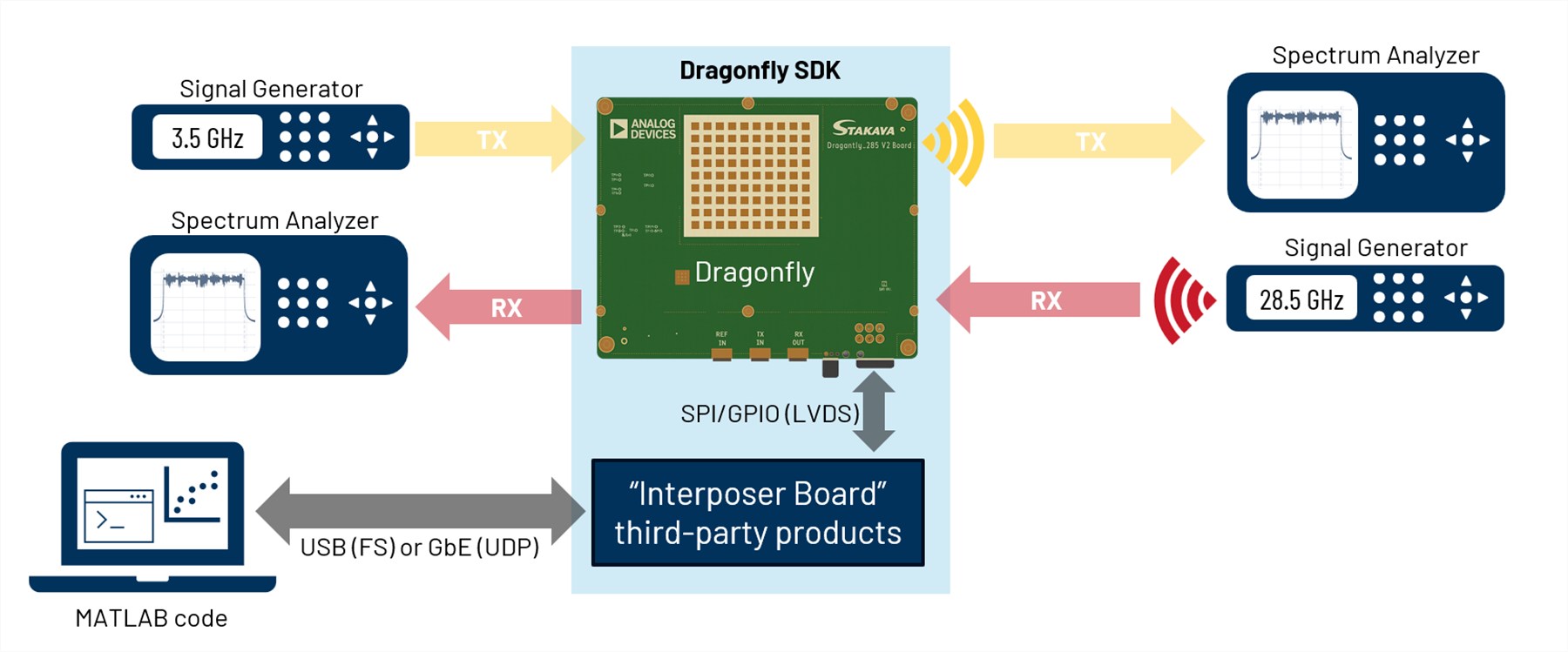
For TX evaluation, the Dragonfly IF input is driven by a 3.5 GHz signal source and the radiated output is observed with an RF signal analyzer. For RX evaluation, a millimeter-wave source illuminates Dragonfly and the downconverted IF output is captured by an analyzer or receiver. The SDK controls the operating mode, beam direction, and gain settings from the host PC.
5. MATLAB Development Environment
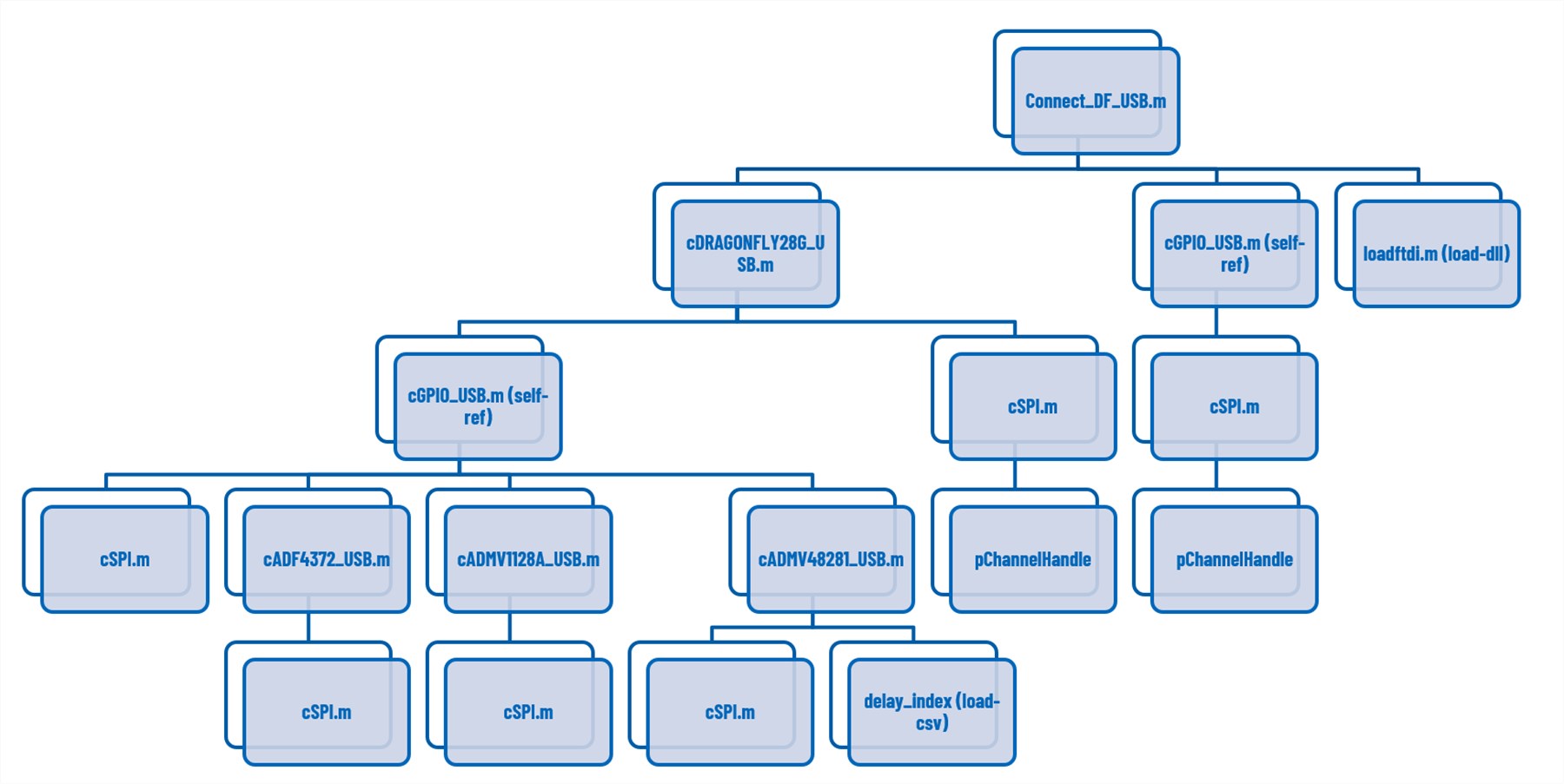
The Dragonfly MATLAB environment provides a unified framework for RF control, calibration, beam management, device monitoring, automated RF characterization, and communication or sensing experiments. Common MATLAB classes abstract the ADF4372/ADF4368 PLL/VCOs, ADMV1128A up/downconverters, ADMV48281 beamformer ICs, SPI transactions, GPIO control, and the SDK interface. Figure 5 illustrates the reference MATLAB software architecture used to control Dragonfly hardware and SDK interfaces.
6. Representative MATLAB Workflows
Receive-Array Phase Calibration
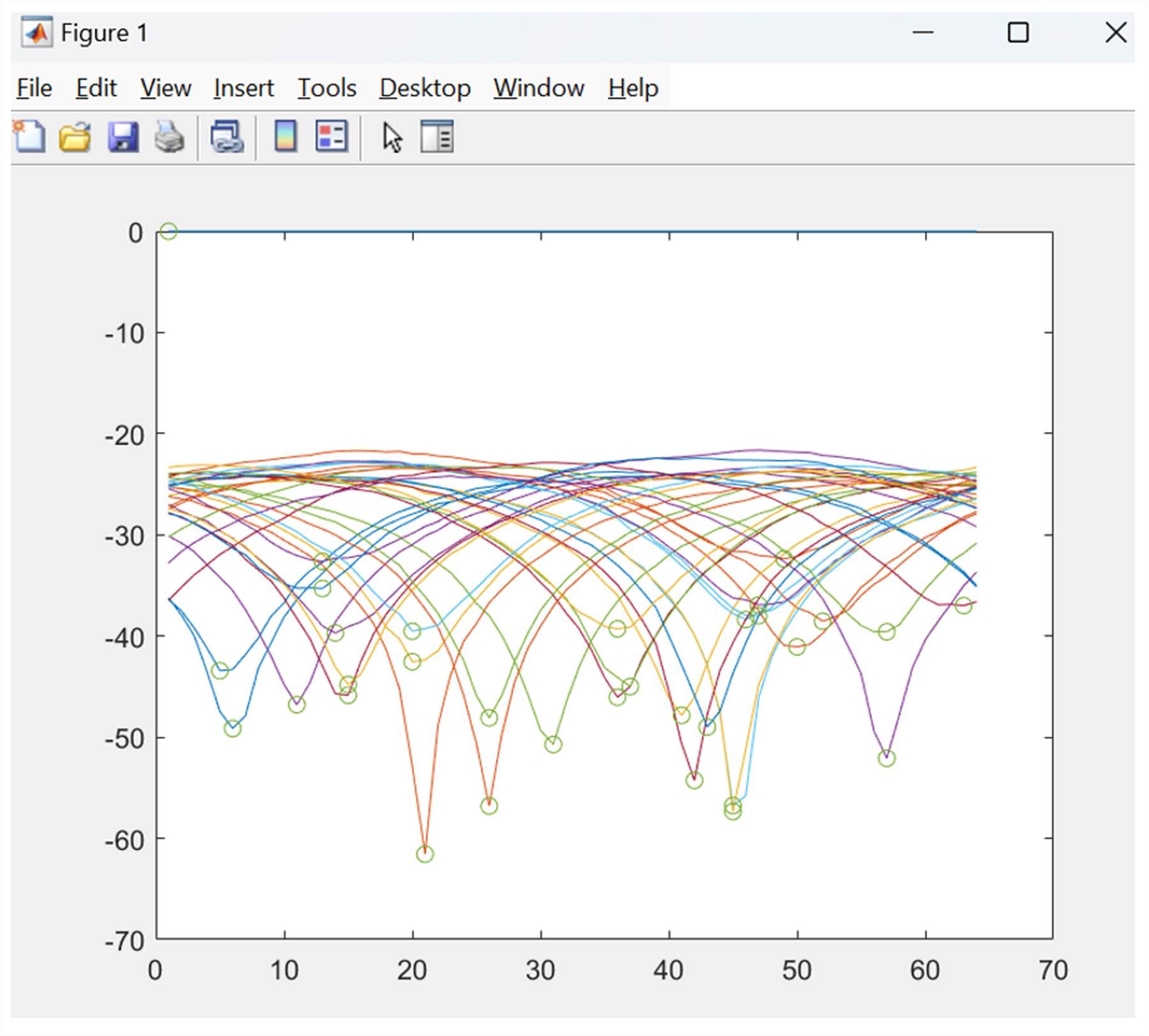
MATLAB supports automatic receive-array calibration using SCPI-controlled RF test equipment. The system sweeps the relative phase offset of each antenna channel, measures received signal power, identifies the null point, and determines the required phase-correction coefficient. The resulting calibration table can be stored and applied during system initialization to improve array coherency and beamforming performance. Figure 6 shows a representative phase-sweep result used to determine the calibration point for each antenna channel.
Beam Pointer Mode
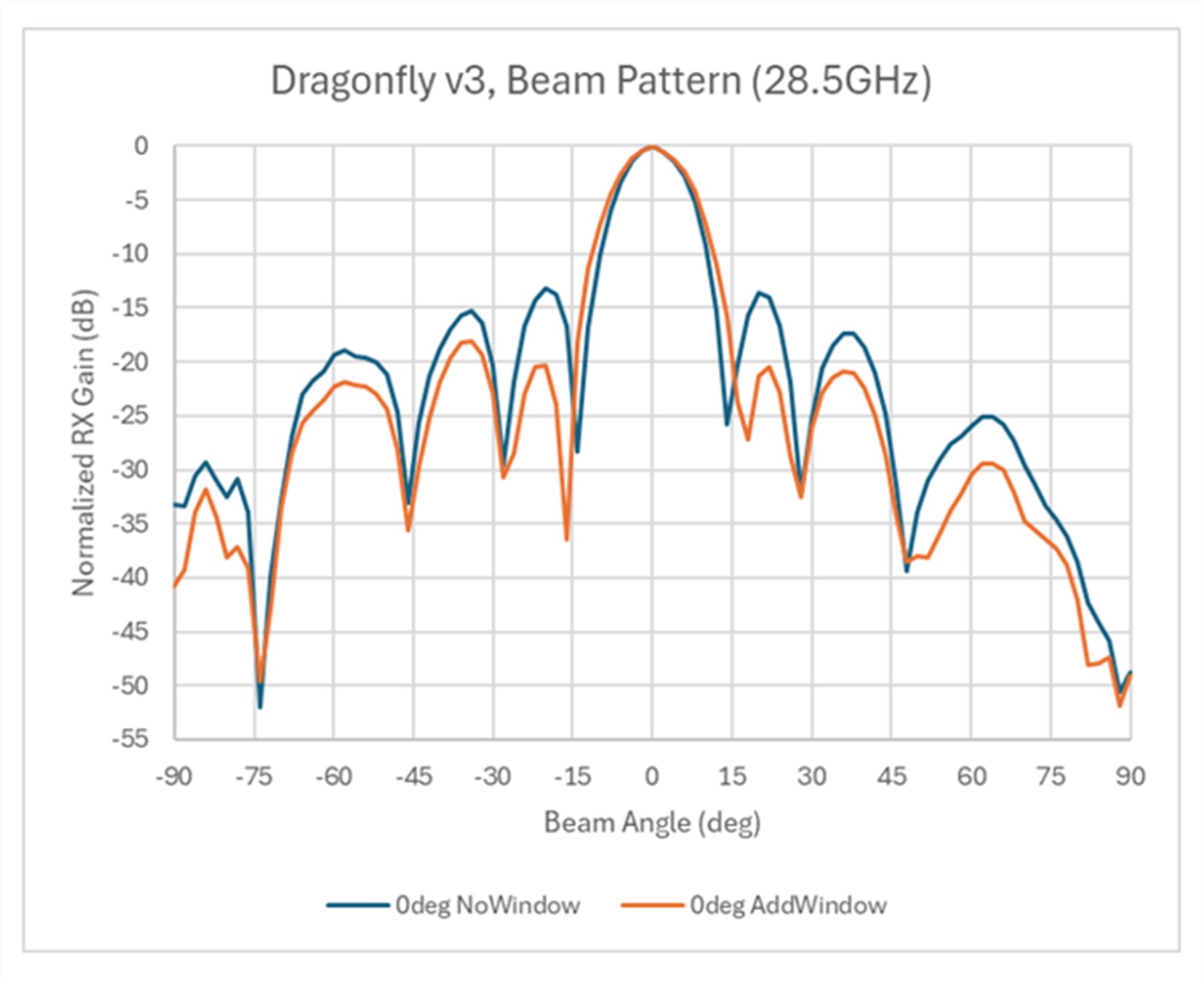
Beam Pointer Mode is the recommended high-speed beam-switching method of the ADMV48281. Beam configurations are stored in on-chip SRAM and recalled through compact pointer commands rather than by rewriting all antenna-channel settings. Up to 1,024 user-defined Beam Points can be stored. MATLAB supports beam-table generation, table loading, rapid beam selection, and evaluation of amplitude-windowing effects. Figure 7 illustrates the effect of MATLAB-configured amplitude windowing on the measured beam pattern.
The common programming model can be used across Dragonfly hardware and SDK configurations. Table 3 summarizes representative functions without exposing device-level implementation detail.
| Category | Representative capabilities |
| System and RF control | Initialization, TX/RX mode, LO, gains, steering, and channel selection |
| Calibration and beam management | Automatic phase calibration, calibration files, Beam Pointer Mode, and beam tables |
| Automated RF characterization | RX gain, TX EIRP, beam patterns, linearity, sweeps, monitoring, and diagnostics |
| Communication and sensing | Waveform control, IQ processing, beam-pair scanning, ranging, Doppler, and visualization |
7. Example Applications
Entry-Level Communication and RSSI-Based ISAC
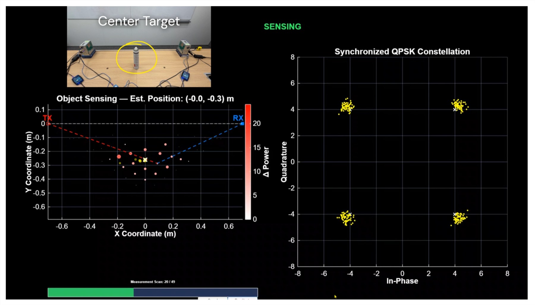
Using two Dragonfly units with ADALM-PLUTO SDRs, users can rapidly construct an over-the-air communication link for beam-management studies and algorithm development. The same configuration has been used for RSSI-based ISAC, where transmit and receive beam combinations are scanned and received-power variations are analyzed to detect targets. The approach provides an accessible introduction to phased-array communication and sensing experiments, although ADALM-PLUTO bandwidth and timing limit precision ranging and coherent Doppler processing.
Advanced OFDM-Based ISAC
For advanced applications, Dragonfly can be combined with synchronized FPGA platforms and ADRV903x/904x wireless-infrastructure transceivers. This architecture supports NR-like OFDM communication together with communication-compatible ranging and Doppler processing while retaining the same 28 GHz phased-array RF front end. MATLAB coordinates waveform generation, beam steering, captured-IQ analysis, communication measurements, and sensing algorithms.
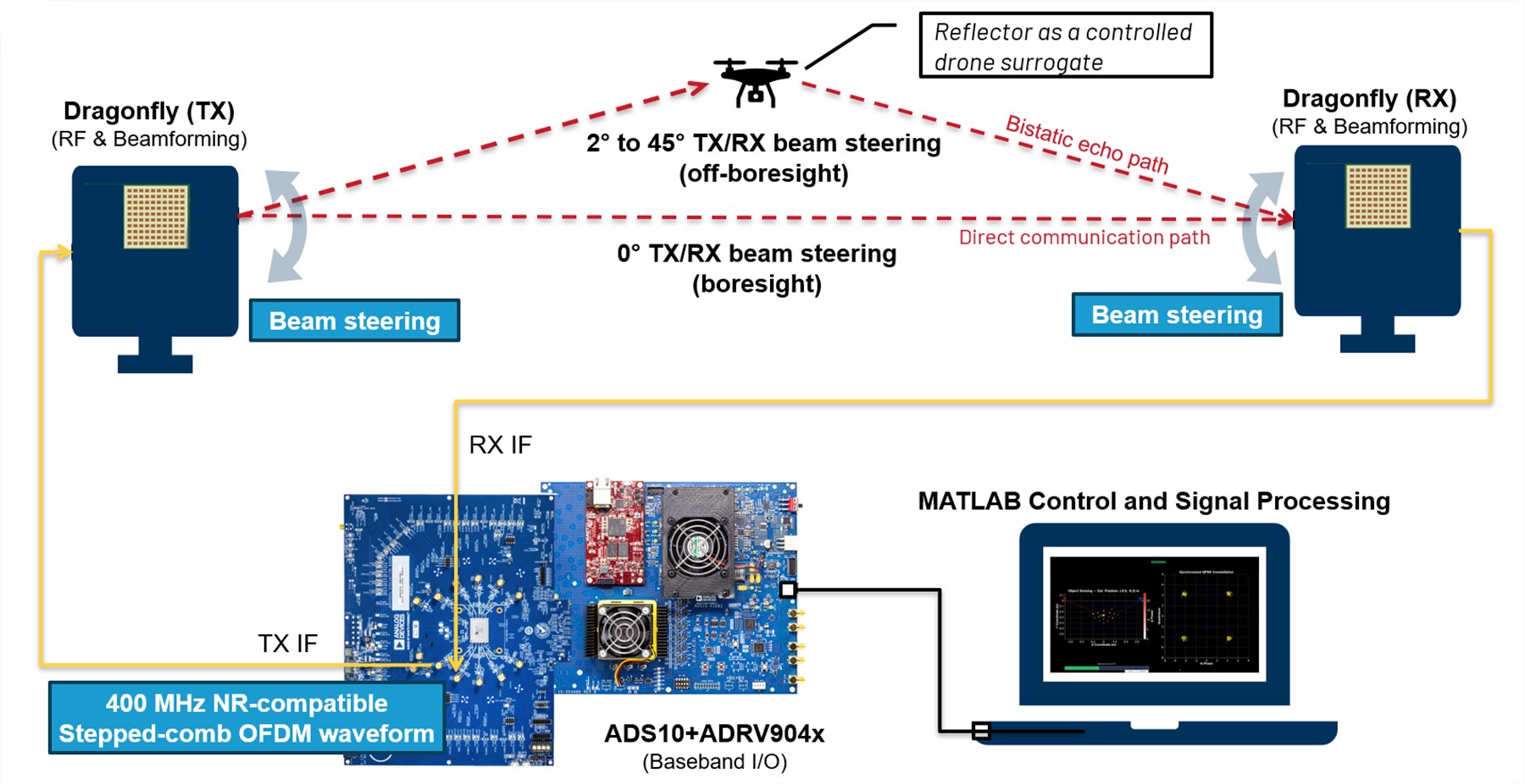
In a measured ADRV904x-based implementation, a 200 MHz NR channel carried a 190.08 MHz occupied stepped-comb OFDM waveform. Controlled measurements produced relative bistatic path-length estimates within 2.1 cm of nominal geometry at a 30-degree beam pair and within 5.0 cm at a 40-degree beam pair. Stationary-target Doppler estimates remained near 0 Hz. These results demonstrate communication-compatible ranging and Doppler analysis on physical hardware. Moving-target Doppler and absolute ranging accuracy remain under validation.
8. Conclusion
Dragonfly bridges the gap between RF component evaluation and complete over-the-air system experimentation. Combining a highly integrated 28 GHz phased-array RF front end with flexible SDK options and a MATLAB-based development environment, the platform provides a practical framework for communication, sensing, and ISAC research using real RF hardware.
Users can begin with accessible SDR-based demonstrations and then scale to synchronized wideband transceiver and FPGA platforms while retaining the same phased-array hardware. This supports activities ranging from beamforming evaluation and RF characterization to NR-like OFDM communication, relative ranging, Doppler processing, and end-to-end ISAC prototyping.
These capabilities also provide a foundation for future AI-enabled sensing and Physical AI research using real-world RF and radar data.
Because waveform generation and signal processing are implemented outside the Dragonfly RF module, the architecture can evolve beyond current OFDM demonstrations toward emerging waveforms such as OTFS and AFDM.
Note: Analog Devices K.K. owns the Dragonfly reference-design data and associated intellectual property. Subject to business justification and applicable agreements, design files may be made available upon approval by Analog Devices. S-Takaya can provide customization, engineering, and manufacturing services based on the Dragonfly architecture.
Contact Information for RFQ
- S-Takaya Electronics Manufacturing Co., Ltd. - https://www.s-takaya.co.jp/en/contact/
- IDAQS Co. - info@idaqs.jp
Dragonfly specifications, availability, and ordering information are subject to change. Please confirm the latest information with the SDK supplier before purchase.