IEEE 802.3af-Compliant Single-Port, Power-Sourcing-Equipment Application
Introduction
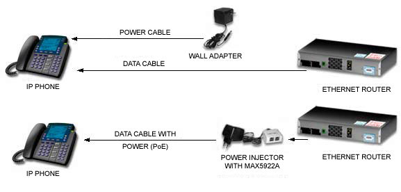
Power-over-Ethernet (PoE) technology enables switch/router and midspan systems, collectively named Power Sourcing Equipment (PSE), to deliver up to 15W of power over the data cable. The power-receiving system is called a powered device (PD). To meet the IEEE 802.3af standard, which governs how the PSE and PD interact, the PSE must detect and classify the PD correctly before powering it. Once the PD is powered, the PSE must sense the PD disconnection and power down the cable promptly. The PSE must also protect the cable and the PD from overcurrent and short-circuit conditions.

Single-Port Circuit for a PSE System
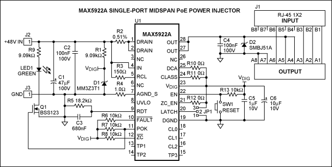
By integrating all required functions, the MAX5922 makes designing a PSE system simple. The circuit in Figure 1 below illustrates a complete PSE design.

Figure 1. Circuit diagram of the MAX5922 power injector
The MAX5922A circuit is configured as a midspan PSE and used as a single-port, midspan power injector. The J1 RJ-45 connector input receives data from an Ethernet router/switch and directly routes the data to the output. The circuit injects 48V into the spare pairs (pins 4, 5, 7, and 8) of the J1 RJ-45 connector output. For an endpoint PSE application, connect the DCA pin to DGND and the output power to the signal pairs with PoE magnetics.
Once a valid PD is detected and classified correctly, this circuit automatically performs PD detection and classification, and turns on the power to the output. CL0-2 reports the classification result. To disable the PD classification function, connect the CLASS pin to DGND.
Output current to J1 is limited to 424mA, ±6%. Reducing the value of the current-sensing resistor, R2, will increase the current limit accordingly, and vice versa. When the output is overloaded or shorted, the circuit acts as a current source, limiting the output current to 424mA. The circuit will turn off the output if the overload/short-circuit condition persists for longer than 60ms. The circuit will restart automatically if JP1 is strap-high (positions 2 and 3), or will latch off if JP1 is strap-low (positions 1 and 2).
Once the output is fully on, POK is asserted and the green LED (LED1) turns on. The circuit continuously monitors the output load current for load disconnection (Zero Current Detection). If the load current drops below 7.5mA (typical) for longer than 350ms (typical), the circuit will turn off the output, assert the active-low ZC signal, and then resume detection and classification. Connect ZC_EN pin to DGND to deactivate the load-disconnect detection function.
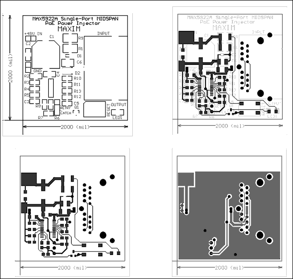
C4 and D2 are protective devices to absorb ESD and cable discharge energy applied to J1. They are also used to clamp any inductive kickback current when the MAX5922 turns off the output after an output short-circuit event. Figure 2 shows the PCB layout for the MAX5922 and Table 1 is the bill of materials.

Figure 2. Circuit PCB layout information
| Load (A) | VOUT (V) Measured | % Error |
| 0 | 0.7215 | 0.2 |
| 12 | 0.7215 | 0.2 |
Features:
- IEEE 802.3af compliance
- RJ-45 data input jack (J1)
- RJ-45 data and power output jack (J1)
- +32V to +60V wide operating input range
- 28V (±7%) turn-on voltage
- 0.45Ω integrated power switch
- Configurable power device (PD), detection and classification
- 424mA (±6%) programmable current limit.
- Configurable zero-current detection with status output
- Classification status output
- Detection-collision avoidance feature for midspan PSE application; configurable for endpoint PSE application
- Power-good status output with green LED indicator (LED1)
- Overcurrent and overtemperature protection with status outputs
- Current-limit foldback with timeout and duty-cycle control
- Selectable latch or autorestart fault management (JP1)
- Single pushbutton reset (SW1)
- Immune to ESD and cable discharge


