要約
Many users of coulomb-counting fuel gauges think of accuracy in terms of percent error. This would be convenient, but the usefulness of a single percentage figure depends on numerous variables, many outside the immediate control of the fuel gauge. Software compensation factors contribute to gauge accuracy, but vary according to the application. It is important that the data fed to compensation algorithms be accurate. Without sufficiently accurate input data, poor gauging accuracy will surely result. From this standpoint, it's helpful to understand the sources of inaccuracy in the fuel-gauging hardware itself.
Additional Information:
Many users of coulomb-counting fuel gauges think of accuracy in terms of percent error. This would be convenient, but the usefulness of a single percentage figure depends on numerous variables, many outside the immediate control of the fuel gauge. Software compensation factors contribute to gauge accuracy, but vary according to the application. It is important that the data fed to compensation algorithms be accurate. Without sufficiently accurate input data, poor gauging accuracy will surely result. From this standpoint, it's helpful to understand the sources of inaccuracy in the fuel-gauging hardware itself.

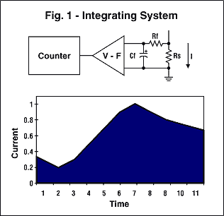
Figure 1. Integrating system.

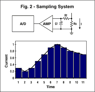
Figure 2. Sampling system.
Coulomb-counting fuel gauges fall into two categories: integrating system and sampling system (see Figures 1 and 2). The MAX1780 advanced battery pack controller and the MAX1660 digitally controlled fuel gauge are examples of integrating fuel gauges. They contain very similar fuel gauges: The MAX1660 is designed for use with a microcontroller, whereas the MAX1780 includes the microcontroller and has the ability to customize the software.
For a given bandwidth, integrating and sampling systems can give equivalent performance. Typically, it is more power-efficient to implement a wide-bandwidth integrating system than an equivalent bandwidth in a sampling system. It can be useful to compare the bandwidth of various solutions. Examining the application circuit and calculating the following can determine the cutoff frequency:

The MAX1780's integrating system gives a bandwidth of approximately 31kHz. An equivalent sampling system would need to sample at least 62,000 times a second to give equivalent performance. Note that any frequencies above the cutoff frequency will be attenuated and not included in the fuel gauging. It is therefore important to understand the system's transient behavior and what load spikes will be present at the battery when choosing a fuel-gauging part.
Other sources of error in the fuel gauge are similar to those found in an A/D converter. These include gain, linearity, input offset, and resolution errors. It is fairly common to see gain and linearity lumped together in the data sheet and specified as a percentage. This is acceptable in the majority of cases and helps keep part costs low by reducing test time.
Input offset error will usually be specified as a voltage. A sense resistor is used to sense the current, therefore:

This error is fixed and does not change with the current sense signal amplitude. Thus, this term contributes more error as measured current becomes small. Increasing RSENSE can reduce the impact of offset error, but the cost of this is increased power dissipation in the application.
Note that some parts have a calibration mode to remove input offset error. This allows compensating for error in the circuitry; however, this parameter will usually drift with temperature and is costly during battery pack manufacture as the compensation can take 10 seconds or more of test time. The MAX1780 uses a chopper-stabilized amplifier to dynamically zero input offset, making it unnecessary to calibrate at the time of battery pack manufacture. This saves the time and the cost of a calibration step.
The last parameter is resolution error. In both sampling and integrating systems, resolution error becomes an issue only when the resolution is as large as the signal level of interest. When this is the case, the resolution error may not cancel because the error source is no longer random. If the resolution of the system you are looking at is close to the sense resistor voltage at the application's minimum current consumption, resolution error may become an issue. An example of such an issue would be a laptop computer with a standby current of 5mA, with a current measurement resolution of 2mA. The example noted has a potential error of 40%.
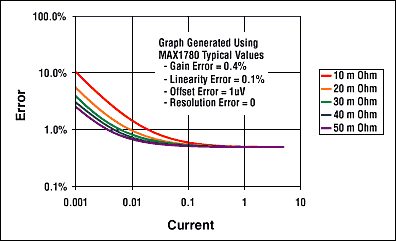
The above parameters allow us to plot MAX1780 fuel-gauge error as a function of current (see Figure 3). Note that the error changes as a function of the sense resistor used and that the effect of input offset is clearly seen at very low currents. Also note that the error shown would be percent error in the fuel gauge, assuming going from full to empty.

Figure 3. Coulomb-counter accuracy as a function of current and RSENSE
Although this information is useful, it is often more helpful to see performance of the gauge in a typical usage scenario. It's possible to take the information calculated above for accuracy as a function of current consumption and to calculate for a given current profile the accuracy of the coulomb counter. This is accomplished by adding the errors at each current consumption and taking into account the time spent at each load current. Individual current consumption error is calculated by multiplying the percent of error for the current of interest by the percent of time the pack spends delivering that current.
The table below gives this error for two different operating profiles. A 3.4 amp-hour battery is assumed in both cases.
Profile A is defined by the following:
| Start-Up Power Surges | 4A | 10% of the Time |
| CPU at Full Speed | 2A | 40% of the Time |
| CPU Throttling | 1A | 50% of the Time |
Profile B is defined by the following:
| Profile A | 50% of the Time | |
| Standby Current | 10mA | 50% of the Time |
Coulomb-Counter-Accuracy Case Study
| RSENSE | Profile A | Profile B |
| 10mΩ | 0.51% | 1.00% |
| 20mΩ | 0.50% | 0.75% |
| 30mΩ | 0.50% | 0.67% |
| 40mΩ | 0.50% | 0.63% |
| 50mΩ | 0.50% | 0.60% |
In summary, although a single percentage accuracy figure may seem attractive, it is seldom representative of real-world performance. It is straightforward to calculate accuracy of a given usage profile for a battery pack once the components of accuracy are known. Knowing this information allows designers to select fuel gauges that meet their needs better.


