Buck-Boost LED Driver Reaches 98% Efficiency, Features Internal PWM Dimming and Spread Spectrum without Flicker
Buck-Boost LED Driver Reaches 98% Efficiency, Features Internal PWM Dimming and Spread Spectrum without Flicker
2016年02月01日
Four-switch converters combine two converters (a buck and boost) into a single converter, with the obvious advantage of reduced solution size and cost, plus relatively high efficiency conversion. High performance 4-switch converters have carefully designed control schemes. For instance, for highest efficiency, a 4-switch converter should operate with only two switches when only step-up or step-down conversion is needed, but bring in all four switches as VIN approaches VOUT. A well-designed buck-boost converter gracefully transitions between the three regions of operation—boost, buck and buck-boost—by taking into account the challenge of combining three control loops—2-switch boost, 2-switch buck and 4-switch operation.
The LT8391 60V 4-switch buck-boost LED driver is designed to drive high power LEDs and to flawlessly transition between 2-switch boost, 4-switch buck-boost, and 2-switch buck regions of operation.
A patent-pending 4-switch buck-boost current-sense resistor control scheme provides a simple, yet masterful, method for the IC to run in peak current mode control in all regions of operation with a single sense resistor. It also allows the IC to run in CCM operation under normal load conditions and DCM operation at light load conditions while maintaining cycle-by-cycle peak inductor current control and preventing negative current.
This new generation buck-boost LED driver features spread spectrum frequency modulation and internally generated PWM dimming. These two features work together—the LT8391 supports flicker-free PWM dimming with either internal or external PWM dimming, even when spread spectrum is turned on (technique patent-pending).
98% Efficient, 50W Synchronous Buck-Boost LED Driver
The LT8391 high power buck-boost LED driver in Figure 1 drives 25V of LEDs at 2A from a wide input voltage range. The 60V buck-boost converter operates down to 4V input. When the input voltage is low, input and peak switch currents can be pushed high. When VIN drops enough to hit the peak inductor current limit, the IC can maintain stability and regulate at its peak current limit, albeit at reduced output power, as shown in Figure 2. This is advantageous from a system design perspective: riding through a low VIN cold-crank condition with a reduction of output brightness is a welcome alternative to cranking up the current limit—and sizing up the inductor, cost, board space and input current—just to keep the lights full brightness during transient low VIN conditions.
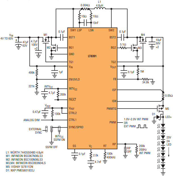
Figure 1. LT8391 4V–60V 4-switch synchronous buck-boost LED driver powers a 25V, 2A (50W) string of LEDs at up to 98% efficiency.
Efficiency of the 50W LED driver in Figure 1 is as high as 98% at its highest point (Figure 2). Over the typical automotive battery input range of 9V to 16V, the converter operates between 95% and 97% efficiency.
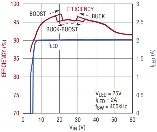
Figure 2. Efficiency and LED current vs input voltage for the 50W LED driver in Figure 1. Efficiency peaks at 98% and doesn’t stray far from that peak, ranging from 95% to 97% throughout the typical 9V–16V automotive input range. Also shown, the LT8391 peak inductor current limit can maintain stable output with reduced output power at low VIN.
With high power MOSFETs and a single high power inductor, the temperature rise for this converter is low, even at 50W. At 12V input, no component rises more than 25ºC above room temperature, as shown by the thermal scans in Figure 3. At 6V input, the hottest component rises less than 50ºC with a standard 4-layer PCB and no heat sink or airflow. There is room to increase power output; hundreds of watts are possible with a single stage converter.
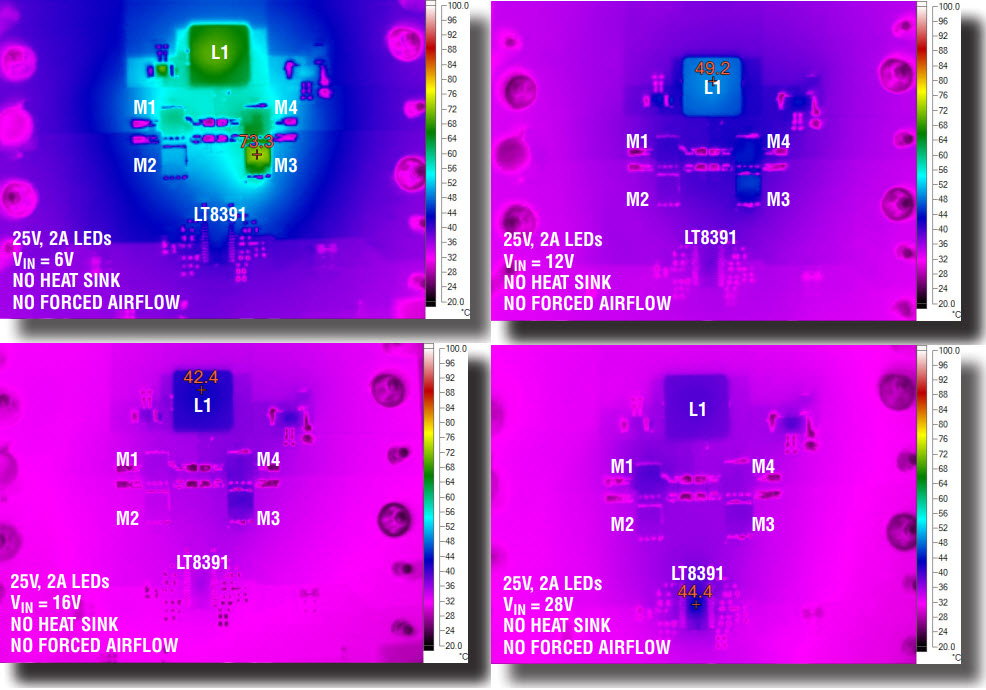
Figure 3. Thermal imaging of the buck-boost LED driver in Figure 1 shows well contained temperature rise for wide ranging VIN.
The 50W LED driver can achieve 1000:1 PWM dimming at 120Hz without flicker. The high side PWM TG MOSFET provides PWM dimming of a grounded LED string on the output. As a bonus, it acts as an overcurrent disconnect during short-circuit faults. The PWM input pin doubles as the standard logic-level PWM input waveform receiver for external PWM dimming and as a novel analog input that determines the internally generated PWM duty cycle.
Internally Generated PWM Dimming
The LT8391 has two forms of PWM dimming: standard external PWM dimming, and internally generated PWM dimming. LT8391’s unique internal PWM dimming feature eliminates the need for external components such as clocking devices and microcontrollers to be able to generate a highly accurate PWM dimming brightness control at ratios as high as 128:1.
The IC’s internally generated PWM frequency, such as 200Hz, is set by a resistor on the RP pin. The voltage on the PWM pin, set between 1.0V and 2.0V, determines the internal generator’s PWM dimming duty cycle for accurate brightness control. The duty cycle of internal dimming is chosen as one of 128 steps and internal hysteresis prevents duty cycle chatter. The better than ±1% accuracy of the internally generated PWM dimming is unchanged in boost, buck and buck-boost regions of operation.
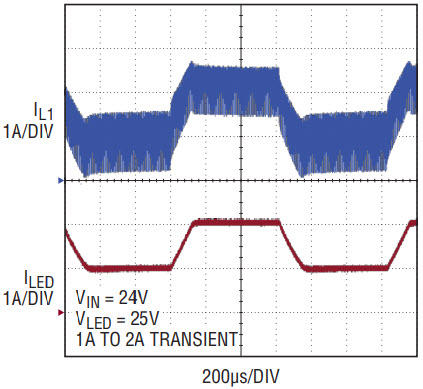
Figure 4. LED current shows a stable response to a CTRL pin driven 1A to 2A.
Spread Spectrum Reduces EMI
Spread spectrum frequency modulation reduces EMI in switching regulators. Although the switching frequency is most often chosen to be outside the AM frequency band (530kHz to 1.8MHz), unmitigated switching harmonics can still violate stringent automotive peak and average EMI requirements within the AM band. Adding spread spectrum to a 400kHz switch mode power supply can drastically reduce the EMI of high power headlight drivers, within the AM band and other regions such as medium and shortwave radio bands.
When activated, SSFM drops the LT8391’s 50W LED driver EMI below both the peak and average EMI requirements of CISPR25 in the AM band (see Figure 5). Average EMI has a more difficult requirement—20dBµV lower than the peak limit. For this reason, the LT8391’s novel SSFM reduces average EMI even more than peak EMI. You can see that there is 18dBµV or more reduction of average EMI, while there is still about 5dBµV of peak EMI reduction. Spread spectrum is very useful in limiting the converter’s effect on other EMI sensitive automotive electronics such as radio and communications.
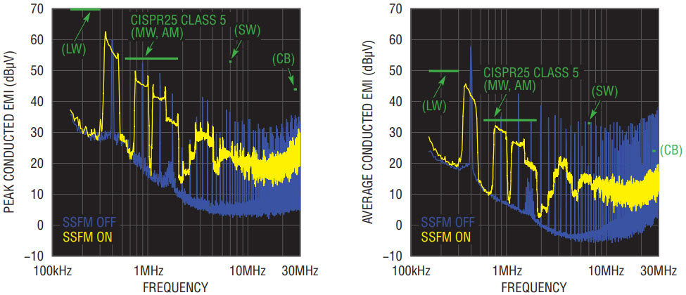
Figure 5. Spread spectrum frequency modulation (SSFM) reduces LT8391 peak and average EMI below CISPR25 limits. Average EMI has even greater reduction than peak EMI with LT8391 SSFM.
In some converters, spread spectrum and flicker-free LED PWM dimming do not work well together. SSFM, a source of changing switching frequency, can look like noise to the outside world—in order to spread EMI energy, smearing non-spread peak values—but it can work together with PWM dimming for flicker-free operation. Linear’s patent-pending PWM dimming and spread spectrum operation is designed to run both functions simultaneously with flicker-free operation, even at high dimming ratios. At 1000:1 PWM dimming with external PWM, and at 128:1 internally generated PWM, spread spectrum continues to operate with flicker-free LED current as shown in the infinite-persist scope photos of Figure 6.
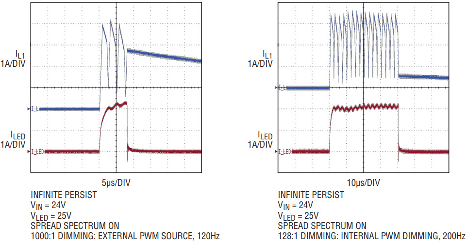
Figure 6. Infinite-persist scope traces show PWM dimming and SSFM working together for flicker-free brightness control with both externally and internally generated PWM dimming.
QFN Package and Dual Package MOSFETs for Compact Buck-Boost Solutions
The LT8391 is available in two package types, a 28-pin leaded FE package, and a smaller 4mm × 5mm QFN. Designers who require access to pins for on-board testing and manufacturing protocols may prefer the 28-pin FE package, but others will be pleased with the small footprint of the QFN. Those that are space-constrained can pair the QFN with a set of 3mm × 3mm or 5mm × 5mm dual package MOSFETs. A synchronous buck-boost controller does not require a lot of board space—very high efficiency can be achieved throughout the main automotive range when dual package MOSFETs are chosen for a very small PCB footprint.
The 4V to 60V input and 16V, 1A buck-boost LED driver shown in Figure 7 uses two such dual-package MOSFETs and the QFN LT8391, achieving greater than 95% peak efficiency. The space savings are shown in Figure 8.
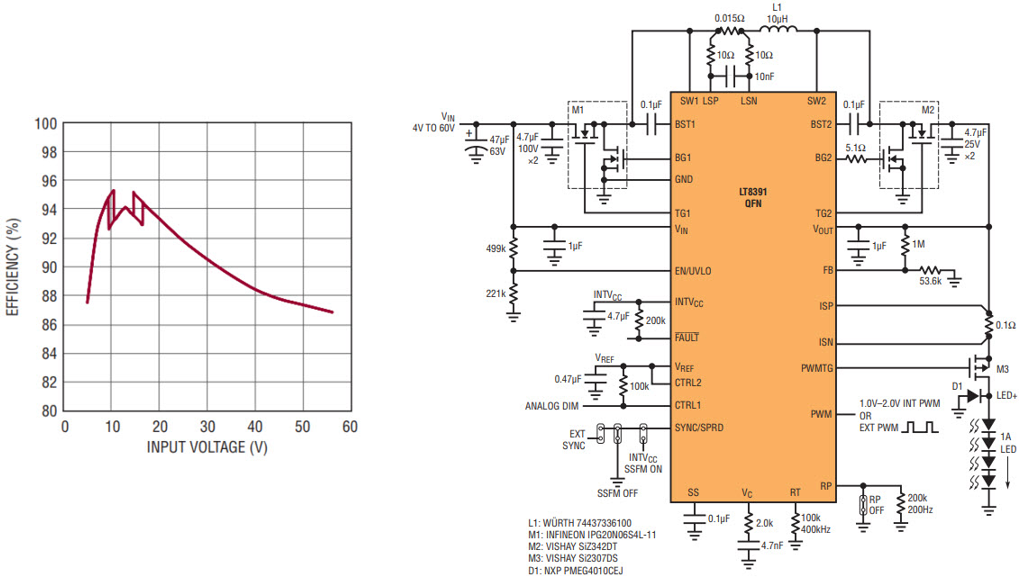
Figure 7. Compact solution featuring the LT8391 in a QFN and dual-package MOSFETs. This 4V–60V input, 4-switch buck-boost converter powers 12V–16V at 1A (16W) LEDs with minimum board space and high efficiency.
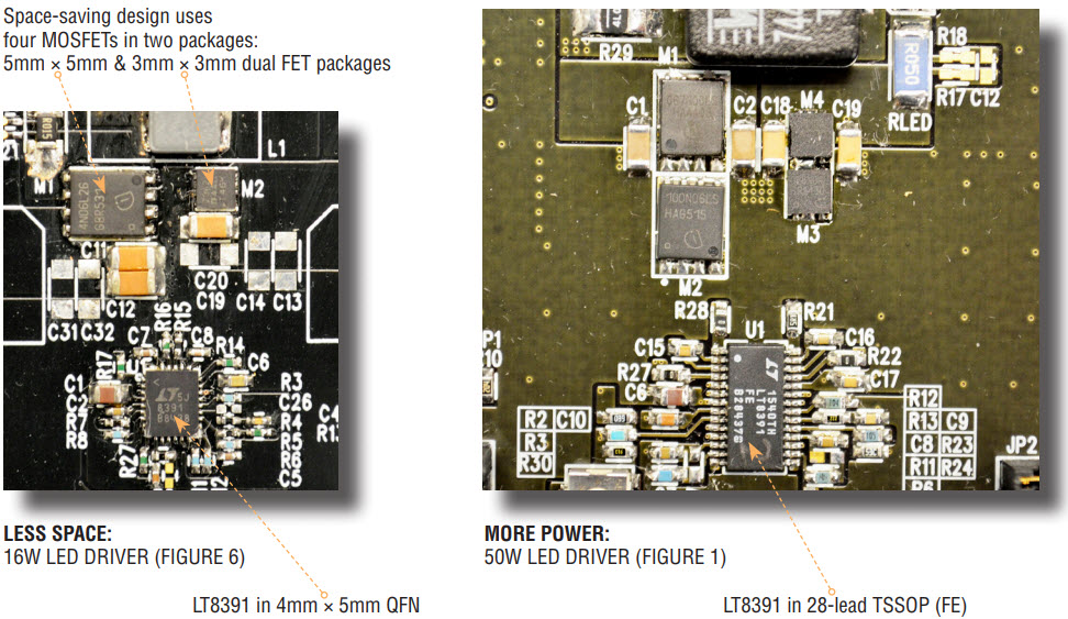
Figure 8. Comparison of the compact solution shown in Figure 6 with the solution of Figure 1. The compact solution, with 5mm × 5mm and 3mm × 3mm dual-package MOSFETs, reduces board space in this 4-switch synchronous buck-boost converter.
The dual package MOSFETs experience only a 15°C temperature rise at high and low input voltage operating conditions, as shown in Figure 9. The dual package MOSFETs can handle 12V, 2A+ (25W) loads while maintaining high efficiency. To further reduce the solution size, the smaller, 3mm × 3mm, dual-MOSFET packages can be used in both locations. For for a slightly higher power rating, or to accommodate higher voltages, the larger, 5mm × 5mm, packages can be used for both dual MOSFETs.
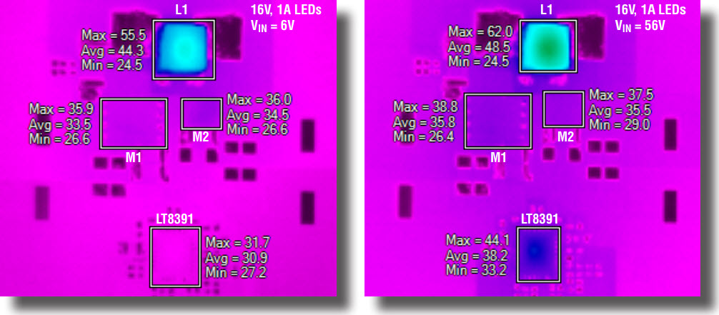
Figure 9. The compact system in Figure 6 exhibits only a 15° temperature rise on the dual MOSFETs at both low and high VIN.
Constant-Current, Constant-Voltage and C/10 Flag for SLA Battery Chargers
The constant-current and constant-voltage capability of LED drivers make them suitable as battery chargers, especially when the driver also has C/10 detection and reporting. The C/10 detection in LT8391 toggles the state of the FAULT pin and can be used to change the regulated charge voltage of a SLA battery to a different, yet regulated float voltage when the charge current drops off.
The LT8391-based, 7.8A SLA battery charger shown in Figure 10 features 97% peak efficiency (Figure 11), and supports constant-current charge, constant-voltage charge and float voltage maintenance in all three regions of operation—boost, buck and buck-boost.
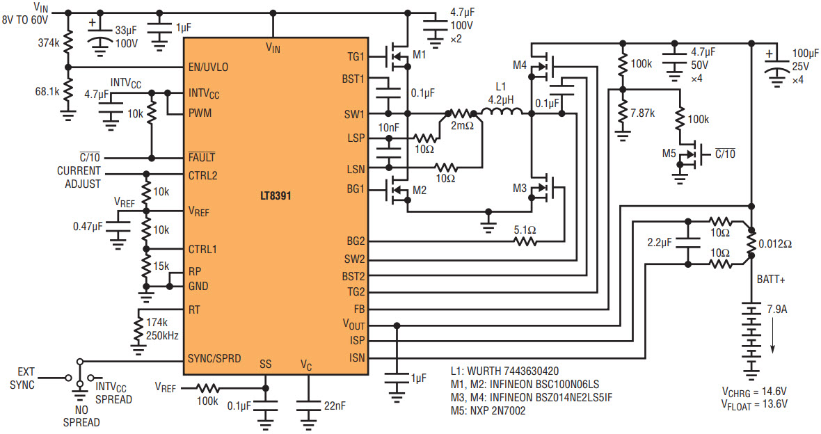
Figure 10. A 7.8A sealed lead-acid (SLA) buck-boost battery charger featuring high efficiency, four small 3mm x 3mm MOSFETs, and both charge and float voltage regulation.
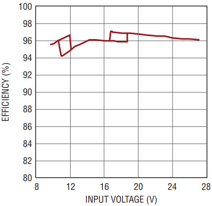
Figure 11. Efficiency of the SLA battery charger.
This charger handles short-circuit, battery disconnect and prevents reverse battery current. DCM operation and the novel peak inductor sense resistor design detect peak current at all times and prevent current from rushing backward through the inductor and switches—a potential pitfall of some 4-switch buck-boost battery chargers that use forced continuous operation.
The charge profile shown in Figure 12 demonstrates the 7.8A constant-current charge state, the constant-voltage charge state and the low current float state of this buck-boost SLA battery charger. Figure 13 shows thermal scans of the charger running at various VIN.
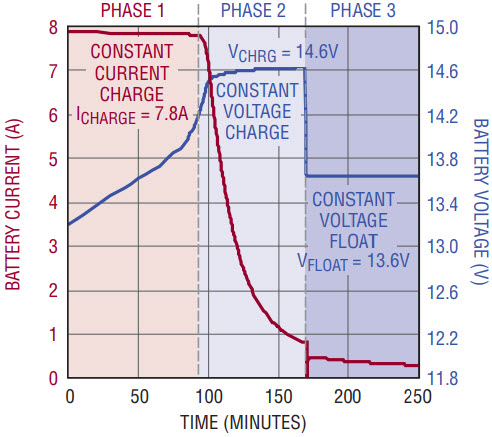
Figure 12. The three charge states of an LT8391 SLA battery charger include constant-current charge, constantvoltage charge and float voltage regulation.
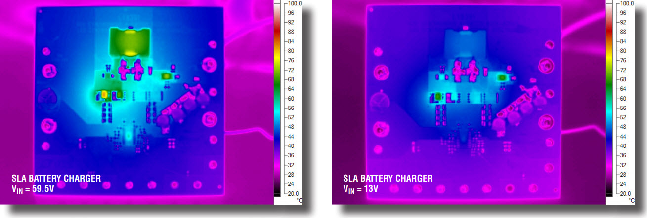
Figure 13. Thermal performance of the SLA battery charger.
Go Green With High Power AC LED Building Lighting
High power LED lighting designs for new buildings and structures is both environmentally friendly and robust. With very low failure and replacement rates, LEDs offer excellent color and brightness control while reducing hazardous waste materials and increasing energy efficiency. Halogen lighting that is typically fitted with 24VAC transformers can be replaced by more efficient AC LED lighting using the LT8391.
The 84W AC LED lighting converter in Figure 14 powers 15V–25V of LEDs at120Hz AC currents peaking as high as 6A. A full-wave rectifier converts 24VAC at 60Hz into a 120Hz half-wave at the input of the LT8391. Four-switch conversion allows the LT8391 to move between boost, buck-boost and buck regions of operation and regulate an AC LED output with high power factor at the input. The waveforms in Figure 15 demonstrate 98% power factor while maintaining 93% efficiency at a very high power. The thermal scan in Figure 16 shows the full wave rectifier.
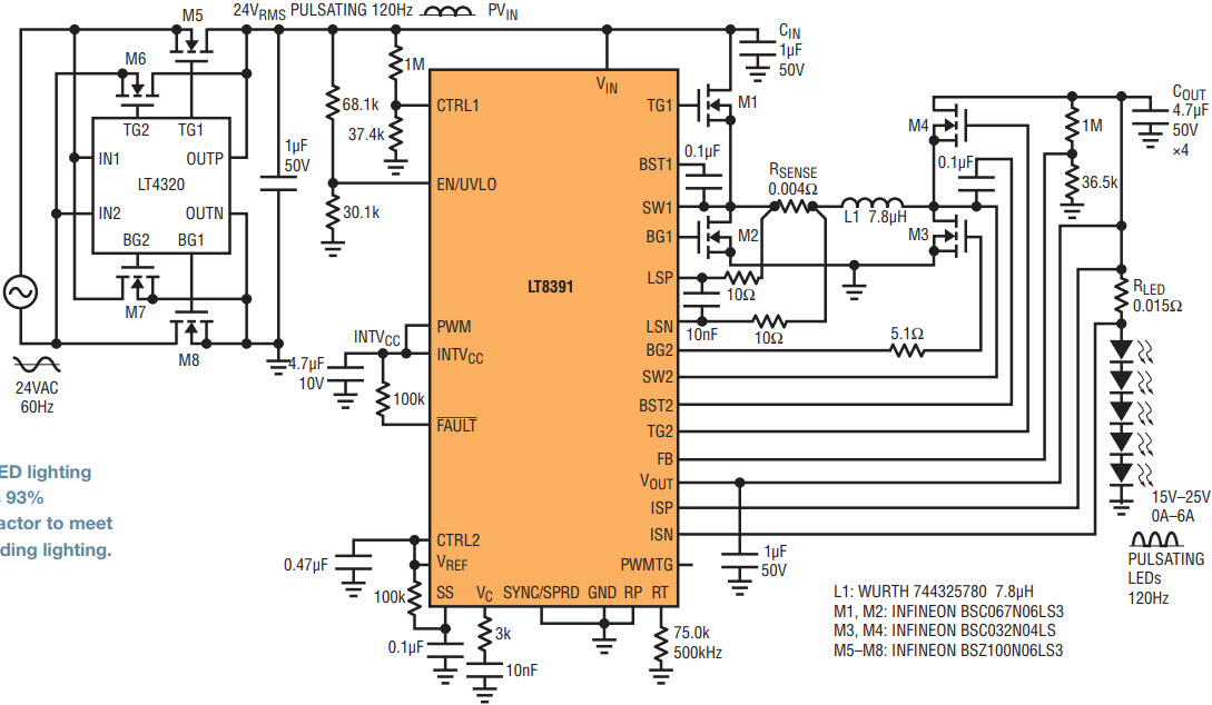
Figure 14. 84W, 120Hz AC LED lighting from 24VAC, 60Hz input has 93% efficiency and 98% power factor to meet green standards in new building lighting.

Figure 15. Input current and voltage waveforms for the 84W, 120Hz AC LED driver demonstrate 98% power factor.
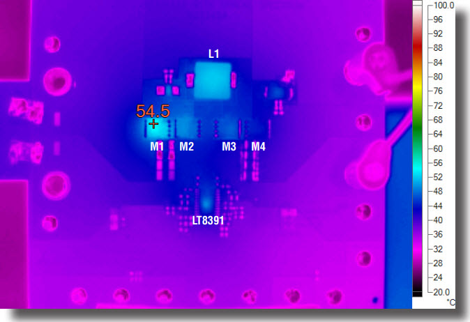
Figure 16. The LT4320 ideal diode used in the 24VAC LED lighting solution stays cool and keeps efficiency high; discrete components remain below 55°C.
Conclusion
The LT8391 60V 4-switch synchronous buck-boost LED driver can power large, high power LED strings, and can be used in compact, highly efficient designs. It features spread spectrum frequency modulation for low EMI and flicker-free external and internal PWM dimming. Synchronous switching offers high efficiency through its wide input voltage range, but it also features DCM operation at light loads to prevent reverse current and maintain high efficiency. The constant-current and constant-voltage operation, combined with its C/10 detection, make the LT8391 suitable for high power SLA battery charger applications with both charge and float voltage termination.
著者について
Keith Szolushaは、アナログ・デバイセズ(カリフォルニア州サンノゼ)のアプリケーション・ディレクタです。2000年からIPSパワー製品グループに所属しています。主に降圧/昇圧/昇降圧コンバータ、LEDやGaNに対応するコントローラ/ドライバなどの製品を担当。また、電源製品向けのEMIチャンバの管理も担っています。マサチューセッツ工科大学で1997年に電気工学の学士号、1998年に同修士号を取得。テクニカル・ライティングの集中コー...


