Single Transistor Reduces LDO Noise by 46dB
要約
A simple RC filter with an external transistor driver rejects LDO noise. A plot of noise density vs. frequency shows that the filter rejects LDO noise by more than 46dB, and achieves a noise floor of 7nV/√Hz.
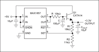
Of the many low-dropout (LDO) regulators providing voltage regulation for electronic systems, some are specifically designed for low noise. The voltage regulator in Figure 1, for example, achieves an RMS noise voltage of about 115µV. Some ultra-low-noise applications such as instrumentation and high-quality audio, however, require even lower noise. To fulfill that requirement, the Figure 1 circuit includes an external transistor and simple lowpass RC filter. Together, they reduce the supply noise by more than 46dB and achieve a noise floor of 7nV/√Hz.

Figure 1. A simple RC filter with an external transistor driver rejects LDO noise.
The RC filter and transistor are inserted in the voltage regulator's feedback loop. The regulator's output voltage (3.3V) is sampled by the R1-R2 voltage-divider and fed back to U1's internal error amplifier at pin 6. The error amplifier compares that voltage against its internal reference voltage, and causes the output to drive Q1 in a direction that maintains voltage regulation. U1's output is noisy, but the noise is filtered by R and C, producing a very quiet voltage at the base of Q1. The result is an extremely low-noise 3.3V output.
The R1 and R2 values are calculated using an equation from the MAX1857 datasheet:
R1 = R2[(VOUT/1.25V) − 1]
The lowpass filter consisting of R and C sets the corner frequency:
fC = 1/2πRC
Above the corner frequency, the lowpass filter rejects noise at about 20dB per decade down to the noise floor. You can reject both low-frequency and high-frequency noise by setting the corner frequency very low, but a low corner frequency also slows the regulator's response time. Thus, because the response time for load transients is much slower than that of the original LDO, the Figure 1 circuit is ideal for steady DC loads without transients. Any load transient with energy above the corner frequency produces a transient voltage at the regulator's output. A large output capacitor (COUT) helps to suppress the noise induced by load transients.
Q1 can be any npn bipolar transistor. A high-gain transistor is preferred because it lowers the base current, thereby allowing a larger R and smaller C. The Q1 shown is a CXTA14 Darlington transistor from Central Semiconductor Corp. Darlington transistors offer high gain but also have a higher VBE voltage, which increases the input-to-output voltage difference. You should choose a transistor with high Early voltage, which rejects source noise at the input.
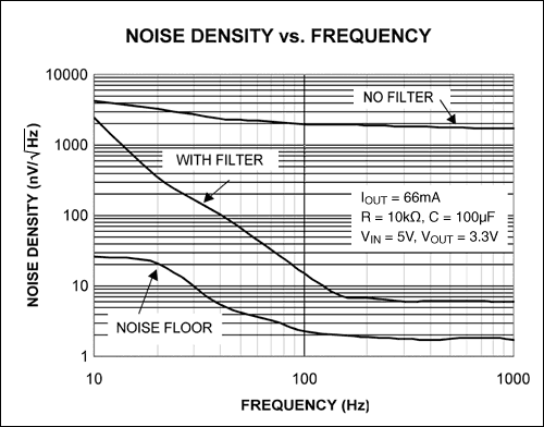
A plot of noise density vs. frequency (Figure 2) shows the noise floor of the measuring instrument (bottom trace) and the output of Figure 1 with and without the RC filter. With the filter in place, the noise floor is about 7nV/√Hz at 200Hz—a noise reduction of more than 46dB.

Figure 2. As shown in this plot of noise density vs. frequency, the simple RC filter in Figure 1 rejects LDO noise by more than 46dB, and achieves a noise floor of 7nV/√Hz.
A similar version of this design idea appeared in the April 14, 2005 issue of Electronic Design magazine.