Design Note 58: A Simple, Surface Mount Flash Memory Vpp Generator
“Flash” type memories add electrical chip-erasure and reprogramming to established EPROM technology. These features make them a cost effective and reliable alternative for updatable non-volatile memory. Utilizing the electrical program-erase capability requires linear circuitry techniques. Intel flash memory, built on the ETOX process, specifies programming operation with 12V amplitude pulses. These “Vpp” amplitudes must fall within tight tolerances, and excursions beyond 14.0V will damage the device.
Providing the Vpp pulse requires generating and controlling high voltages within the tightly specified limits. Figure 1’s circuit does this. When the Vpp command pulse goes high (Trace A, Figure 2) the LT1109 switching regulator drives L1, producing high voltage. DC feedback occurs via the regulator’s sense pin. The result is a smoothly rising Vpp pulse (Trace B) which settles to the required value. Trace C, a time and amplitude expanded version of Trace B, details the desired settling to 12V. Artifacts of the switching regulator’s action are discernible, although no overshoot or poor dynamics are displayed.

Figure 1. All Surface Mount Flash Memory Vpp Generator.

Figure 2. Waveforms for the Flash Memory Pulser Show No Overshoot.
This circuit is well suited for providing Vpp power to flash memory. All associated components, including the inductor, are surface mount devices. As such, the complete circuit occupies very little space (see Figure 3). In the shutdown mode the circuit pulls only 300μA. Output voltage goes to VCC minus a diode drop when the converter is in shutdown mode. This is an acceptable and specified condition for flash memories and does not harm the memory. A 0V output is possible by placing a 5.6V Zener diode in series with the output rectifier (Figure 4a). An alternative configuration, suggested by J. Dutra of LTC, AC couples the output to achieve a 0V output (Figure 4b). Both of these methods add component count, decrease efficiency and slightly limit available output current. They are unnecessary unless the user desires a 0V output on the Vpp line.

Figure 3. Simple Flash Memory Pulser Uses All Surface Mount Components.

Figure 4a.

Figure 4b.
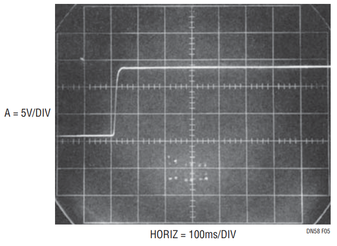
A good question might be; “Why not set the switching regulator output voltage at the desired Vpp level and use a simple low resistance FET or bipolar switch?” This is a potentially dangerous approach. Figure 5 shows the clean output of a low resistance switch operating directly at the Vpp supply. The PC trace run to the memory chip looks like a transmission line with ill-defined termination characteristics. As such, Figure 5’s clean pulse degrades and rings badly (Figure 6) at the memory IC’s pins. Overshoot exceeds 20V, well beyond the 14V destruction level. The controlled edge times of the circuit discussed eliminate this problem. Further discussion of this and other circuits appears in LTC Application Note 31, “Linear Circuits for Digital Systems” and LTC Demo Manual DC019, “Flash Memory Vpp Generator.”

Figure 5. An “Ideal” Flash EPROM Vpp Pulse.

Figure 6. Rings at Destructive Voltages After a PC Trace Run.
