RS-485 Adapter Converts Data Lines from Full- to Half-Duplex
要約
An adapter circuit consisting of an RS-485 transceiver (MAX3076 or MAX13086) and a voltage monitor used as a timer (MAX641X) allows an existing point-to-point full duplex circuit to function in a more-complex point-to-multipoint half-duplex system.
A similar version of this article appeared in the June 21, 2007 issue of Electronic Design magazine.
Multiprotocol interface ICs (such as the MAX3162 from Analog Devices) can be used to connect a UART to an RS-485 bus architecture called point-to-point full-duplex (PTP-FD). The PTP connection usually requires that drivers and receivers be kept constantly enabled, and therefore "present" on the line. When such a circuit board must fit into a point-to-multipoint half-duplex system (PTM-HD), the entire board (usually) must be redesigned (Figure 1).

Figure 1. The adapter circuitry indicated by "?" lets you incorporate existing PTP-FD communication links into an existing PMP-HD system.
A simple trick, however, can adapt an existing PTP-FD board (providing a single link between two terminals) for use in the more complex PTM-HD architecture (one master and multiple slaves, connected by multiple links), thereby preserving and making reusable the hardware already designed and manufactured.
A PTP-FD slave board is always ready to "hear" interrogation/ command signals from the PTM-HD master unit, but it answers only when it recognizes its own address. To avoid any effect on the signal-transmission path of the half-duplex side, every adapter (operating only on the slave board's TX output) maintains itself in the quiescent state. When a slave output starts to transmit, the adapter becomes active and transfers that data to the central unit.
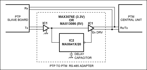
The adapter circuit consists of two devices as shown in Figure 2. The RS-485 receiver portion of IC1 (MAX3076E or MAX13086) is always enabled. It senses the TX output of the PTP slave board, drives the timer (IC2, MAX641X), and enables IC1's RS-485 transmitter, which is normally kept in a quiescent state.

Figure 2. This RS-485 interface-adapter circuit converts point-to-point full-duplex data lines to point-to-multipoint half-duplex lines.
The timer is triggered when the slave board TX output makes a high-to-low transition (a start bit). It then enables the transmitter via the En DRV signal, and maintains the En DRV state for a time interval imposed by the delay capacitor. The timer is retriggered by the next high-to-low transition (data bit) of the input signal (Figure 3). The value of the delay capacitor depends on the TX input transitions coming from the PTP slave board, the time between data packets, and the switching time between channels (the slave boards to be addressed).

Figure 3. These waveforms illustrate timing relationships for the RS-485 adapter circuit of Figure 2.