One Megahertz Adaptable Power Supply Meets XENPAK MSA Specification
要約
This application presents a DC-DC converter that meets the XENPAK Multisource Agreement (MSA) criteria for a fiber-optic module that conforms to the 10 Gigabit Ethernet standard defined by the IEEE® 802.3ae. The MAX1953 step-down controller has 0.8V feedback threshold, works with 3.3V input voltage, and switches at 1MHz. Ceramic capacitors and small inductors lower cost.
The XENPAK Multisource Agreement (MSA) defines a fiber-optical module, which conforms to the 10 Gigabit Ethernet standard as laid down by the IEEE 802.3ae. This app note presents DC/DC converters that meet the adaptable power supply (APS) specification of XENPAK MSA Revision 2.1 (at the time of writing).
The APS is capable of providing supply voltage rail from 0.9V to 1.8V to the XENPAK transceiver plug-in module. This voltage is available on the host PCB, and is set by a resistor that resides in the transceiver plug-in module. Table 1 below lists this resistor value for the corresponding APS voltage per XENPAK MSA specification revision 2.1 and the measured APS voltage of circuit of Figure 1 with ±1%; resistors.
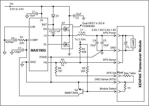
To meet the requirements, the step-down controller must have feedback threshold of 0.8V, and be able to work with input voltage as low as 3.3V. The circuit shown in Figure 1 meets this requirement while switching at 1MHz to allow the use of all ceramic capacitors and small inductors for lower cost.

Figure 1. 3.3VIN, 0.9V to 1.8V, 0.4A to 1.8A out.
The circuit provides APS power to the transceiver module as shown conceptually in the dashed line box. If the module is not plugged in Q2 turns on and pulls the COMP pin low to shut off the converter. When the module is plugged in the 1kΩ resistor will pull the base of Q2 low to turn it off and enable the converter. RSET in the module is part of a feed-back divider network that sets the nominal APS voltage as indicated in Table 1. If the APS set pin is open, the output is 0.8V, which is the feed-back threshold voltage. The APS sense pin provides remote sensing to compensate for distribution voltage drop. If APS sense is open R2 pulls FB up and output voltage goes to zero. This prevents APS voltage from going high and possibly damaging the load.
| RSET (Ω) | XENPAK specification VNOM (V) | Measured APS voltage of Figure 1 (V) | Percent of deviation of measured voltage vs. specified nominal (%) |
| 6810 | 0.9 | 0.909 | 1 |
| 3160 | 1.0 | 1.007 | 0.7 |
| 1820 | 1.1 | 1.111 | 1 |
| 1180 | 1.2 | 1.210 | 0.8 |
| 806 | 1.3 | 1.305 | 0.38 |
| 536 | 1.4 | 1.407 | 0.5 |
| 348 | 1.5 | 1.506 | 0.4 |
| 210 | 1.6 | 1.604 | 0.25 |
| 97.6 | 1.7 | 1.703 | 0.18 |
| 0 | 1.8 | 1.813 | 0.7 |
As shown in Table 1, measured APS voltage is well within the ±3%; of XENPAK specification. The APS voltage is measured at the load side (across CL) with simulated XENPAK module per Figure 1 with resistive load, and a 180µF, 4V special polymer (Panasonic #EEFUE0G181R) decoupling capacitor (CL). XENPAK specifies a 200µF maximum value for this capacitor. The load and CL are connected to the output of the APS with a pair of 6' long wires to simulate remote sensing. The ripple voltage measured across the load decoupling capacitor (CL), is less than 2mV peak-to-peak. When measured at the APS output (across C4, C5), it is less than 3mVRMS and 10mV peak-to-peak. Both are well within the 40mVRMS specified by XENPAK.
Load and line regulations were measured for both the maximum APS voltage of 1.8V and the minimum of 0.9V to have 1mV deviation for 0.4A to 1.8A and for 3.0V to 3.6V respectively.