Modified LDO Regulator Sinks PECL-Termination Current
要約
Adding a transistor to a standard PECL-termination circuit boosts the sink current to 4A.
An earlier PECL-termination circuit (published as a design brief in the January 19, 2004 issue of Electronic Design) offered an output-current capability of 400mA—enough to terminate about 14 differential pairs of PECL outputs. That circuit has been revisited on behalf of designers who require more than 400mA. Adding a single resistor increases the available output current by 300%, and adding a transistor boosts the output capability to 4A.
Adding Rsink to the original circuit (Figure 1) increases the current-sinking capability as follows. Knowing the output voltage is 1.3V, set the resistance to sink current at the lower end of the desired 400mA range. If the midrange current is 1A, for example, set the resistance to sink 800mA (1.3V/0.8A = 1.625Ω), which allows the output current to range from 0.8A to 1.2A. Make sure the resistor is rated to handle the power. This method works well if the desired output-current range is known and is no more than 400mA. (If IOUT is less than 0.8A, the IC will go out of regulation; if it is more than 1.2A, it will go into current-limit-protection mode, also resulting in a loss of regulation.)

Figure 1. Adding one resistor to the basic circuit shifts the output-current range higher, but the range remains only 0.8A to 1.2A for 400mA, for example.
A better method for increasing the output current is to add a pnp transistor at the output (Figure 2). Pin 5 of the IC sinks base current from the transistor, which maintains regulation by sinking current through the collector. Current is limited by the transistor characteristics. With the components shown (including a TIP42B pnp power transistor) the maximum output current is 4A. The Figure 2 circuit (unlike that of Figure 1) remains in regulation up to the maximum level of current. Choose a high-gain transistor for high output current, but avoid Darlington transistors—the VBE of a Darlington is about 1.4V, which is more than the 1.3V output voltage.

Figure 2. A better method for increasing output current is to add a pnp transistor to the output. (A TIP42B power transistor yields an output range of 0 to 4A.)
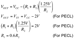
The equations for calculating the values of feedback resistors R1 and R2 are same as for the original circuit:
This design idea appeared in the June 20, 2005 issue of EE Times.