Linearizing Microwave Transmission Power Amplifiers Using the SC1894
要約
This document is an introduction to linearizing a microwave transmission system PA using Maxim's SC1894 RF PA Linearizer (RFPAL) from 4GHz to 80GHz. It includes basic system design considerations to implement a linearized microwave amplifier and the effects of Automatic Transmit Power Control (ATPC) on the SC1894 performance.
Introduction
Overview
This document is an introduction to linearizing a microwave transmission-system PA using Maxim's SC1894 RF PA Linearizer (RFPAL) from 4GHz to 80GHz. It includes basic system design considerations to implement a linearized microwave amplifier and the effects of automatic transmit power control (ATPC) on the SC1894 performance.
Digital microwave transmission systems require low bit-error rates (BER) and must not transmit excessive adjacent-channel power (ACP), which would interfere with other wireless services. With respect to transmitter signal fidelity, BER is directly affected by the modulated-waveform error-vector magnitude (EVM). Reducing the modulated-waveform EVM is a primary goal in all transmitter design and the final stage power amplifier (PA) can degrade the EVM when operating near maximum power creating intermodulation products (IMD). These IMD products are the dominant components of ACP. A traditional solution to avoid the IMD problem is to back off (reduce) the power until the IMD distortion is at an acceptable level. Using backoff results in an inefficient transmitter design and, depending on the waveform, one cannot achieve the desired linearity specification regardless of how far the PA is backed off.
Maxim's SC1894 can improve the PA linearity and minimize EVM, IMD, and ACP levels without sacrificing the PA output power. Furthermore, predistortion linearization allows a PA to operate at significantly higher efficiency compared to another PA operating in backoff with similar output power levels. In the case of GaN devices that can be inherently nonlinear, predistortion is often the only available method to achieve the required EVM and ACP levels. By enabling operation at maximum PA output power while minimizing EVM and ACP, the SC1894 devices provide the system with lower BER, better efficiency, and lower system and operating costs.
IMPORTANT: In order to achieve optimal performance, refer to [4] in the References section.
Adding RF Predistortion to Microwave Transmission
Microwave point-to-point manufacturers have products that cover many frequency ranges from 4GHz to 80GHz. These radios transmit a fully occupied single carrier with an instantaneous signal bandwidth ranging from 3.5MHz to 112MHz. Modulation modes vary from BPSK to 1024QAM and peak-to-average ratios (PAR) of 4dB to 8dB. As the signal bandwidth and modulation complexity increase, so does the need for predistortion in order to meet system linearity requirements. The system output power is typically controlled through lookup tables calibrated at the OEM factory. The power-control lookup table is used to control the various VGA gains in a desired sequence. These lookup tables are then used to set the antenna output power at each operating frequency, temperature, and power level. Transmit output power is typically operated over a 25dB power range.
System Block Diagram
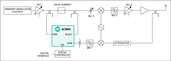
To use the SC1894 in microwave systems operating at frequencies greater than 3.8GHz, the SC1894 must be placed in the IF section of the transmitter as shown in Figure 1. (Typical microwave systems operate using an IF at frequencies between 350MHz to 3.5GHz.)

Figure 1. Simplified microwave application system block diagram using the SC1894.
The application represented in Figure 1 can be adapted to many different transmitter configurations having different output powers, gains and frequencies. Due to the many variations possible, the exact implementation of ALC1, ALC2, and ALC4 is left to the discretion of the system designer. These functions can be implemented as either fixed or variable gain amplifiers/attenuators. The main requirement is that the elements in the up-conversion and feedback down-conversion paths do not significantly contribute to the overall distortion of the system so that the SC1894 only compensates PA-related nonlinearity.
System-level Linearity Guidelines:
- The relative IMD level of the feedback down-conversion path should be at least 10dB less than the IMD desired at the PA output. For example, if the desired PA IMD is -55dBc (typical requirement in many microwave systems), other parts in the down-conversion path should have IMD ≤ -65dBc.
- The relative IMD level of the up-conversion path should be at least 10dB less than that of the uncorrected PA. For example, if the PA IMD is -40dBc, other parts in the up-conversion path should have IMD = -50dBc.
Component-level description and guidelines:
- Mixers. The input power to the mixers is typically < < 0dBm to ensure linear operation. The IMD signals generated by the mixers should be < -60dBc. To achieve this, IMD performance typically requires that the input power to the mixer be 30dB lower than the input IP3 of the mixer.
- ALC1. Used to adjust the RFIN-port power when the PA is set to transmit maximum peak envelope power (PEP) and to dynamically control the output power of the transmitter. When the PA is set to maximum power, RFIN BALUN input power should be +6dBm PEP maximum, over temperature and aging. ALC1 is also used to dynamically control the output power of the transmitter when RFIN ATPC is implemented (discussed later).
- ALC2. Used to dynamically control the output power of the transmitter when RFOUT ATPC is implemented (discussed later).
- ATPC. ATPC power control is best done using the ALC1 gain control element. (In an IDU/ODU1 design, ALC1 is often located in the IDU.)
- FBatten. Adjusts the RFFB power levels when the transmitter power output is set to maximum PEP. At this maximum transmitter power level, the RFFB-port input power should be typically -4dBm PEP with allowances for temperature variation and aging (refer to the SC1894 data sheet for exact values). In this fashion, as ATPC is used to vary the transmitter power, the optimum dynamic response of the SC1894 is achieved. FBatten is set once and then held at the same gain allowing the RFFB power to change in direct proportion to the output power.
- ALC4. Adjusted to keep the mixer input power in a linear range under all gain settings.
- External digital controller (required). Controls the VGA elements. The controller also communicates with the SC1894 to send handshake commands during ATPC power changes.
- BPF1 and BPF2. Up-conversion systems require filtering to eliminate image and LO signals from the transmitted signals. For the down conversion to RFFB, a filter might be needed, depending on the frequency plan. The SC1894 can be programmed to monitor just the operating frequency range and ignore image frequencies. Refer to the corresponding SC1894 data sheet, hardware design guide, and release notes for additional detail on setting these frequency monitoring limits (freqMIN and freqMAX).
All filters should have flat gain and group delay over the total IMD frequency range. Gain or group delay variation increases memory2 effects; thus, reducing correction. The SC1894 injects an “inverse IMD” correction signal into the output PA and this signal should be passed through the up-conversion chain with little or no distortion. Likewise, the SC1894 measures the PA IMD using the down conversion path and any distortion on this path reduces the accuracy of this IMD measurement.
All system power changes are sensed at the RFFB input.
Automatic Transmit Power Control (ATPC)
Point-to-point microwave link propagation losses are nominally low by design, with the radio operating at an output level well below maximum power. This is by regulatory requirement to reduce interference while still maintaining the needed SNR or BER level for transmission integrity. However, operating the link with just enough power to maintain good BER makes the system vulnerable to fading conditions such as heavy rain and multipath. When a fading condition is detected, ATPC compensates for the fading condition by increasing the PA power up to 100dB/s in order to maintain the SNR/BER rate required by the system.
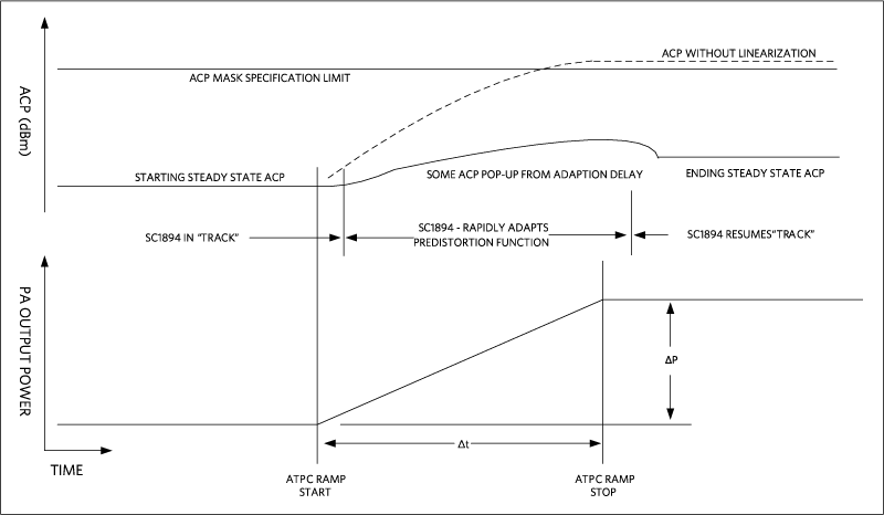
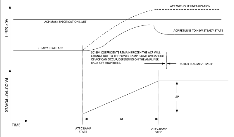
IMD is a function of PA power. As the power increases, the predistortion system must track or adjust to the new operating point as fast as possible. The rate of power change and the location of gain change are the key parameters driving special processing by the SC1894. See Figure 2 and Figure 3 for an overview of the ATPC power-ramp sequences.
ATPC with the SC1894
To accommodate ATPC power-level changes when the PA is actively linearized, Maxim developed specialized firmware (FW) that allows the SC1894 to better correct ACP during and after PA power changes. In optimized (default) mode, any change of the power level into RFFB initiates a full recalibration of the internal SC1894 gain settings. Maxim has developed a fixed gain mode called "smooth adaptation" mode. In this mode, there is no recalibration of SC1894 internal gain when the power is changed.
For this discussion, the two locations in a microwave transmission system where RF power changes can occur are before and after the SC1894. When the RF power changes before the SC1894 RFIN port, we call this "RFIN ATPC". When power changes after the RFOUT port, we term this; "RFOUT ATPC."
Both RFOUT ATPC and RFIN ATPC require the use of smooth adaptation mode.
Refer to [5] and [7] in the References section for further details on ATPC implementation with SC1894.
Option 1: RFOUT ATPC
With RFOUT ATPC, the PA power is changed using ALC2 and ALC4 (see Figure 1). Changing PA power with ALC2 and ALC4 also changes the predistortion signal from the SC1894, requiring new correction settings to be calculated and incurring a delay in adjusting to the new power level. To avoid recalculating correction with every power-level change, Maxim has developed FW that performs a look up table (LUT) function using factory-trained correction coefficients. The FW also continuously saves the best correction settings at each power level as it operates in the field, updating the LUT with these settings.
Best solution for system signal to noise ratio, but not the best for dynamic behavior.
Option 2: RFIN ATPC (Ideal For the SC1894)
Smooth adaptation mode allows the SC1894 to continue uninterrupted ACP correction, but only when power is changed before RFIN using ALC1. Using RFIN ATPC and Smooth Adaptation mode, the RF input power to the SC1894 tracks the PA input power, dB-for-dB. Likewise, the SC1894 correction signals (generated from RFIN using Volterra series coefficient multiplication) tracks the PA IMD levels almost exactly. This feature greatly improves the dynamic power performance of the SC1894 predistortion. An LUT is also implemented with RFIN ATPC, but the variations of correction coefficients (for the Volterra series) are very small and the performance of RFIN ATPC with either the LUT or frozen coefficients at maximum PA power is almost the same.
(Performance of RFIN ATPC with standard wireless FW when coefficients are frozen at maximum power is very similar. However, reading and writing an LUT is not available with this FW so the ATPC FW is a better choice when an LUT function is required.)
With the SC1894 smooth adaptation mode, RFIN ATPC power changes using ALC1 before RFIN providing the best dynamic behavior, but not ideal for system signal-to-noise ratio.

Figure 2. ATPC Power Ramp Sequence when SC1894 is active in TRACK mode.

Figure 3. Power Ramp Sequence when SC1894 correction is frozen at max power.
Option 3: RFIN/RFOUT ATPC (Recommended)
Since a power amplifier is able to meet most linearity requirements when operated in backoff, in general, only about the top 3dB to 6dB of the PA power range requires predistortion. Below this point, the SC1894 correction can be frozen until the power returns to this range. ALC1 is used for at least the first 3dB to 6dB of PA backoff from maximum power. Thereafter, ALC2 and ALC4 can be used if adaptation is frozen.
Option 3 allows the microwave system architect to allocate the ATPC gain reduction to different parts of the system to maintain the minimum required system signal-to-noise ratio and achieve best dynamic range performance.
Smooth Adaptation Mode
Smooth mode is enabled by factory calibrating the SC1894 when the system is operating at maximum RMS power and maximum PEP.
- Select a test signal with the lowest peak-to-average ratio (PAR) of all required signals. By using the lowest PAR signal at maximum system PEP, we are assured of calibrating at the highest possible RMS power level while still keeping the test signal peaks below the PA saturation point. In fact, the PEP of the test signal controls the maximum RMS level that can be achieved with good linearity.
- Set the system to this maximum power and then adjust the power levels into the SC1894 to meet the PEP limits specified in the data sheet at RFIN and RFFB (at all temperatures and frequencies).
- Using either the Maxim test GUI or system SPI commands, initiate a "Maximum Power Calibration" sequence. The SC1894 automatically finds the best gain settings for predistortion at this maximum power level.
Refer to [6] in the References section, the SC1894 SPI programming guide, for details on smooth-mode calibration.
Standby Transmitter Operation
Often, a standby system is deployed in parallel to the main system. The standby system PA is therefore inactive for long periods of time, but can be driven to PMAX at any time. The same FW used to perform the LUT function for ATPC can be used for this case to accelerate convergence time of the backup PA by properly seeding the coefficients before enabling adaptation. Any LUT must have frequency, modulation, power, and temperature as indices.
Footnotes
1 IDU = Indoor Unit, ODU = Outdoor Unit
2 Memory effects are PA transfer function changes that occur in time. Classic transfer function theory often refers to a constraint that systems should be linear and time invariant. Nonlinear systems violate this constraint, they contain nonlinearity’s and the transfer function can vary in time (have memory effects).
参考資料
- ETSI 302 217-1 V1.3.1 (2010-01) regarding Automatic Transmit Power Control (ATPC)
- ETSI 302 217-2-2 V1.4.1 (2010-07)
- SC1894 data sheet
- Designing_Linearizable_RF_PA_using_RFPAL
- SC1894_Microwave_FW4.1.07.00_Release_Notes
- SC1894_SPI_Programming_Guide
- SC1894_Microwave_SPI_Addendum