AN-1377: Gain and Offset Temperature Drift Compensation for the AD7403/AD7405
Introduction
The AD7403/AD7405 are high performance, second-order, Σ-Δ modulators that convert an analog input signal into a high speed, single-bit data stream, with on-chip digital isolation based on Analog Devices. Inc., iCoupler® technology. The AD7403 and the AD7405 feature CMOS and LVDS digital interfaces, respectively. This application note describes a method of using a collocated, system integrated, temperature sensor with the AD7403/AD7405 to calibrate out a large degree of offset and gain error drift over temperature. In motor control applications, the drift of offset and gain errors over temperature is of particular concern because it contributes to system instability. The compensation method described in the Compensation Technique section can reduce the drift figure specified in the AD7403/AD7405 data sheets by up to 30% for offset drift and 90% for gain error drift.
Offset and Gain Error Effects
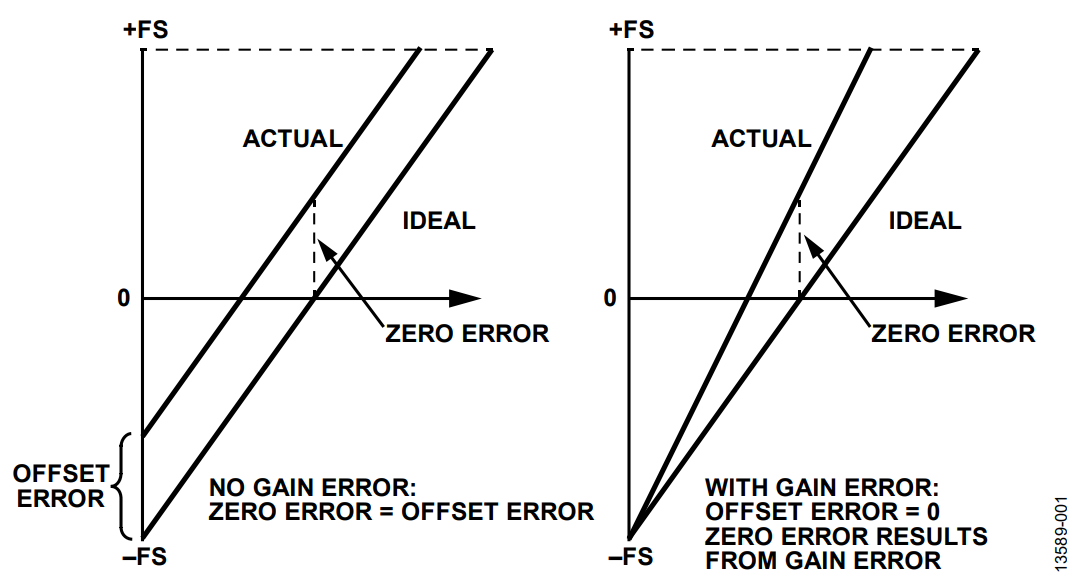
Offset and gain errors are common sources of dc error in ADCs and contribute to the total unadjusted error (TUE) of the converter. Figure 1 shows how offset and gain errors affect an ADC transfer function. Most data converter systems have these errors calibrated out by the user at ambient temperature, but offset and gain error also drift with respect to temperature. In motor control applications, the offset and gain error drift of an ADC, like the AD7403/AD7405, can contribute to system errors such as torque ripple.
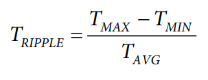
Torque ripple is generally undesirable in motor control applications because it leads to vibrations, noise, and excessive wear in machines. It also causes a deterioration of speed control performance because it acts as a load disturbance. Torque ripple is defined as the percentage difference between the maximum torque, TMAX, and the minimum torque, TMIN, relative to the average torque, TAVG.
In an ac motor drive, torque ripples result in speed ripples in the motor output. Offset errors in current measurements cause the torque of a motor to oscillate at the stator electrical frequency, fE. Asymmetric gain (or scaling) errors cause the torque of a motor to oscillate at 2 × fE.
Variations in offset and gain with temperature are more difficult to compensate for than absolute offset and gain error. Compensating for offset and gain error drift is achievable for converters with linear and predictable drift profiles, provided that the system temperature is known.

Compensation Technique
Many current measurement systems for motor control applications incorporate temperature sensors to monitor for abnormal conditions. It is possible to use this temperature information to perform offset and gain error drift compensation, particularly where the converter has a known, predictable (linear) drift profile. The AD7403/AD7405 isolated Σ-Δ modulators have drift profiles well suited to compensation techniques. The following analysis was carried out using a sample of 18 devices, which included both typical parts and devices across process variations. The plots display results for a sample of typical devices.
Offset Error Calibration
By looking at a sample of typical devices over the full operating temperature range, it is possible to determine the drift profile of the ADC. Figure 2 shows the offset drift profile for a sample of AD7403 devices.

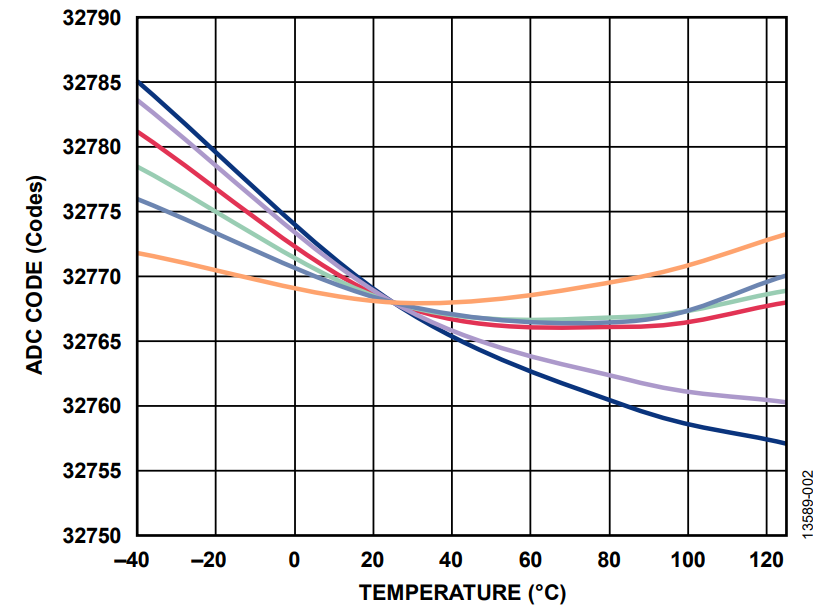
The AD7403/AD7405 have a typical figure of 1.6 µV/°C for offset drift vs. temperature. As shown in Figure 2, the devices have a relatively linear and predictable drift characteristic over the entire temperature range. Knowing the drift profile, and having calibrated out the absolute offset error of the devices at 25°C, it is possible to apply a compensation factor to the profile to make it as flat as possible. The compensation factor pivots the profile about the 25°C calibration point. Experimentally, the compensation factor that yielded the best offset drift performance for the AD7403/AD7403-8/AD7405 is shown in Table 1.
| Offset Drift | AD7403 | AD7403-8 | AD7405 |
| Compensation Factor (µV/°C) | 0.84 | 1.8 | 0.5 |
| Improvement (%) | 12.5 | 33.5 | 11.5 |
For example, looking at the AD7403, the original mean offset drift improved from 1.24 µV/°C to approximately 1 µV/°C, a 12.5% improvement over the specified performance for the device.

Gain Error Calibration
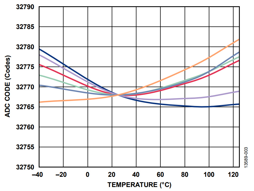
A similar and even more effective compensation method can be applied to the gain error drift of both the AD7403 and the AD7405. The gain error of the devices over temperature is very linear with a tight distribution, lending itself to a large degree of compensation. Figure 4 shows the gain drift profile for the AD7403 over the full operating temperature range.

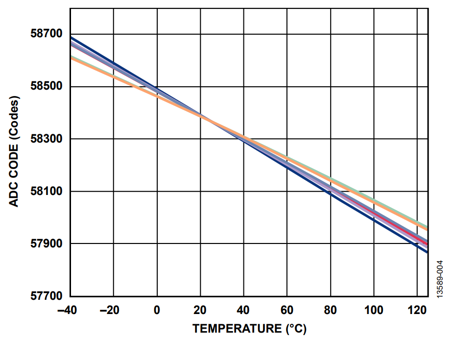
Experimentally, the compensation factor that yielded the best gain drift performance for the AD7403/AD7403-8/AD7405 is shown in Table 2. For example, looking at the AD7403, the original mean gain drift improved from 42.1 µV/°C to 4.9 µV/°C, an 88% improvement.
| Gain Drift | AD7403 | AD7403-8 | AD7405 |
| Compensation Factor (µV/°C) | 40 | 36 | 28 |
| Improvement (%) | 88 | 91 | 80 |
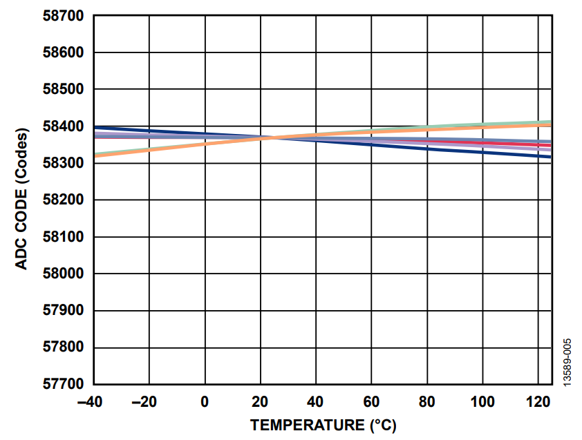
Figure 5 shows the temperature compensated gain drift profile achieved after applying the previous compensation factor.

著者
