AN-1277: Utilizing the Cyclic Redundancy Check Block of the ADV7850
Introduction
The ADV7850, the first complete audio/video front-end device developed by Analog Devices, Inc., targets the professional and consumer video markets. The device incorporates a frame checker block that employs cyclic redundancy checking (CRC). This application note outlines the background of the frame checker function and details how it is utilized.
Cyclic Redundancy Checking
A CRC is a redundancy check invented by W. Wesley Patterson in 1961 (Peterson, W. W. and Brown, D. T. [January 1961]. "Cyclic Codes for Error Detection". Proceedings of the IRE, Volume 49, Issue: 1, Pages 228 to 235). A CRC detects errors in digital data and is used primarily in data transmission systems. For example, a 32-bit CRC transmits data over Ethernet.
Many different CRC implementations exist, but the same basic premise persists; the data transmitter (Tx) calculates and appends a number of check bits (often referred to as a checksum) to the data before it is transmitted. This is implemented by dividing the data to be transmitted by a fixed binary number. The remainder of the division then forms the checksum. The receiver can determine if the check bits agree with the data using an inverse of the transmitter side calculation. If the checksum calculated on the receiver side does not match that calculated on the transmitter side, the receiver concludes that an error occurred in the data transmission and requests a retransmission of the data.
The ADV7850
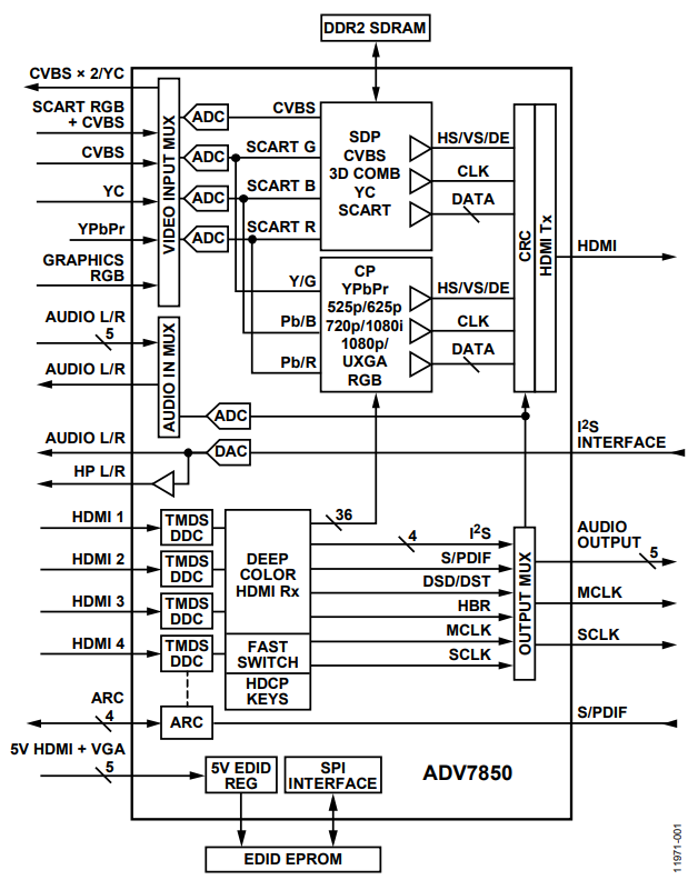
The ADV7850, the first complete audio/video front-end device developed by Analog Devices, targets the consumer and professional video markets. The device incorporates a four-input HDMI receiver that supports video resolutions up to 4000p × 2000p at 30 Hz, a video and graphics digitizer capable of operating at up to 170 MHz, a high speed serial video output, a 3D comb video decoder, and an audio codec. In addition to being a comprehensive single-chip audio/video front end, the ADV7850 also incorporates a frame checker that employs a CRC. The frame checker, which does not require any external hardware to operate, is located at the input to the ADV7850 Tx (see Figure 1), allowing the entire video path for an HDMI input to be analyzed. This feature is not available for analog inputs due to least significant bit (LSB) errors introduced by the analog-to-digital converters (ADCs).

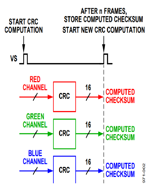
The frame checker in the ADV7850 is designed, utilizing the CRC-16-CCITT polynomial (x16 + x12 + x5 + 1), to analyze each of the data channels coming into the ADV7850 Tx (green = Channel 0, blue = Channel 1, and red = Channel 2) for a user configurable number of frames (up to 254). When the frame checker is enabled, it simultaneously computes a checksum for each channel (see Figure 2) over the specified number of frames (ranging from 300,000 pixels for 480p to 8,000,000 pixels for 4000p × 2000p).

When the frame checker has completed its analysis, it reports a set of results for each of the channels (HDMI transfers data on the red, green, and blue channels). For a static input, performing multiple iterations of the CRC provides a consistent result. A single pixel difference between two frames (up to 16,000,000 pixels of data) yields different checksum results. Whether the pixel difference occurs due to noise on the source, noise induced intermittently in the transmission medium, or the incorrect configuration of the ADV7850, any failure is detected.
The CRC in Video Applications
A video signal chain does not mimic the typical Ethernet style data transmitter and receiver pair. In a video signal chain, the link is unidirectional; therefore, it is not feasible for a video sink (for example, a television) to request a video source (for example, a Blu-ray™ player) to retransmit an incorrectly received data frame. To account for this asymmetry, a CRC operates in a slightly different manner. The obvious location in the video signal chain to perform the analysis is in the video receiver, given the limitation already outlined. The video receiver can apply a CRC to subsequent frames of incoming video data, with the only caveat being that the incoming video data must be static in its content. Examples of static content include a SMPTE video test pattern and a DVD player menu screen.
The CRC is constructed using the known polynomial (for example, x16 + x12 + x

If the remainder stays the same for subsequent frames, the frames are the same and the system is operating at a combination of hardware and software settings that yield optimum system performance. If the checksums for subsequent frames do not match, the frames are inconsistent and the system must be optimized.
Utilizing the CRC
To use the frame checker in the ADV7850 to perform a CRC test, these steps must be followed:
- Configure the number of frames requiring the CRC analysis (1 to 254) using the CRC_FRAME_NUMBER[7:0] control (see Table 1).
- Enable the CRC calculation using the CRC_ENABLE bit (see Table 2).
- Toggle the CRC block reset from high and back to low using the CRC_RESET bit (see Table 3).
- Depending on the size of the incoming video frame and the number of frames selected for analysis, the calculation takes some time to be completed. Wait a recommended minimum of 500 ms for the test to complete.
- Using the CRC_RESULT[15:0] (see Table 4) and CRC_READBACK_SEL[1:0] (see Table 5) controls, read back and log the CRC result for each of the HDMI channels: Channel 0, Channel 1, and Channel 2.
- Toggle the CRC block reset from high and back to low using the CRC_RESET bit (see Table 3).
- Wait a minimum of 500 ms for the test to complete.
- Using the CRC_RESULT[15:0] (see Table 4) and CRC_READBACK_SEL[1:0] (see Table 5) controls, read back and log the CRC result for each of the HDMI channels: Channel 0, Channel 1, and Channel 2.
After two CRC checksums have been calculated and logged, a comparison can be performed. If the results are consistent, the static video pattern in both frames received by the ADV7850 CRC block are the same. If the results are not consistent, the static video pattern in both frames received by the ADV7850 CRC block differ and there may be a signal integrity or configuration issue.
CRC Related Controls
The following are the controls for the frame checker:
- CRC_FRAME_NUMBER[7:0]
- CRC_ENABLE
- CRC_RESET
- CRC_RESULT [15:0]
- CRC_READBACK_SEL[1:0]
CRC_FRAME_NUMBER[7:0], IO Map, Address 0x2D[7:0]
This signal selects the number of video frames over which the CRC is calculated.
| CRC_FRAME_NUMBER[7:0] | Description | |||
| 0x01 to 0xFE | Number of frames for CRC calculation (0x07 = default) | |||
CRC_ENABLE, IO Map, Address 0x2C[7]
This bit enables the CRC calculation.
| CRC_ENABLE | Description | |||
| 0 | CRC calculation disabled (default) | |||
| 1 | CRC calculation enabled | |||
CRC_RESET, IO Map, Address 0x2C[6]
This signal resets the CRC block.
| CRC_RESET | Description | |||
| 0 | No action (default) | |||
| 1 | Reset the CRC block | |||
CRC_RESULT[15:0], IO Map, Address 0x2E[7:0]; Address 0x2F[7:0]
This signal reads back the CRC calculation result.
| CRC_RESULT[15:0] | Description | |||
| 0x0000 to 0xFFFF | CRC calculation result (0x0000 = default) | |||
CRC_READBACK_SEL[1:0], IO Map, Address 0x2C[5:4]
This signal changes the data source of the CRC calculation result readback.
| CRC_READBACK_SEL[1:0] | Description | |||
| 00 | HDMI Channel 0 (default) | |||
| 01 | HDMI Channel 1 | |||
| 10 | HDMI Channel 2 | |||
著者


