資料ライブラリ
AN-013: Motion Control Profile Parameterization
Motion Control Basics
Motion control regulates position, velocity and acceleration of actuators like electric motors and its load. Although motion control profiles could be quite complex moving multiple axes, this contribution focus on different motion profiles for one axis carrying a load from one point to another. Pure motion control is mostly done by the ramp generator, the heart of the motion controller.
Understanding relevant motion parameters
As a first step, you should understand which parameters have a direct or indirect influence on the motion profile.
| Parameter | Description | Dimensions | Calculations |
| Position P | A definite characterized location of a point in space in relation to an arbitrary reference origin. | ||
| Distance s | The absolute difference of the positions of two points P1 and P2. | L (L = length) |
 |
| Velocity v | The distance which is covered by a point for a certain time period Δt. | L·T-1 (T = time) |
 |
| Acceleration a | The rate of change of velocity with time. An acceleration which is lower than 0 is also called deceleration d. | L·T-2 |  |
| Jerk j | The rate of change of acceleration with time. | L·T-3 |  |
In some of our applications, the parameter bow appears, which is the same as a constant j(t). A bow value < ∞ is used to generate a soft transition for a load, leading to reduced system resonances to acceleration value changes. System resonances or overshoots act like an additional load on the motor, thus reducing the available useful portion of motor torque. Furthermore, the necessary time span to fade away system resonances could be diminished by lower bow values as well, thus giving the opportunity to start early with further actions if a whole system stop is required. As a result, so-called S-shaped ramps for the velocity profile are generated.
Specific motion profiles
In the following, different motion profiles are introduced with its advantages and disadvantages.
Constant velocity
The simplest way to drive a load is to set a constant velocity to the electric motor if motion is required (the solid line in Figure 1). Due to the use of velocity commands only (a = ∞/0 and bow = ∞/0), motion control is easy, but also not precise due to the time finite behavior of systems and its load which have to accelerated to the required velocity. This results in fluctuating time delays ta, td for acceleration which are dependent on system and load. Differences of the real-world velocity of the system and load are displayed in Figure 1 with a dotted line. Due to the relationship between velocity and distance, precise positioning is not possible without further regulation.
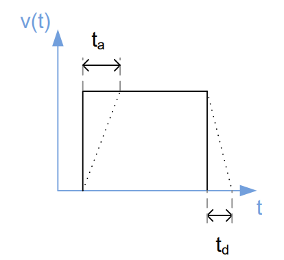
Figure 1. Constant velocity ramp (solid line) with real behavior of the system (dotted line).
Constant acceleration – Trapezoidal velocity ramp
To predict the acceleration rates ta and td, a trapezoidal velocity ramp could be created. Thereby, the velocity of the system will be increased and decreased linearly with a constant gradient which are the acceleration value aMAX and the deceleration value dMAX to the maximum velocity vMAX (Figure 2). Hence ta, td and the distance s could be calculated precisely:

System resonances will still occur, but for many systems it could be neglected.
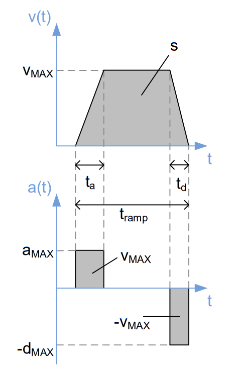
Figure 2. Trapezoidal velocity ramp with corresponding acceleration curve (similar to the motion profile of TMC457 with bow_max = 0).
S-shaped velocity ramps for minimum system resonances
In some cases, system resonances should be avoided as much as possible. Therefore, a gradual modification of the acceleration parameter a has to be provided. By taking the bow parameter into account, overshoot problems could be eliminated. Hence mechanical vibrations could be reduced to a minimum. Disadvantages are a higher complexity for velocity and positioning calculation and a slower positioning due to lower acceleration value than the maximum possible acceleration. Figure 3 depicts the velocity, acceleration and bow ramps for a constant change (bow) of a. These S-shaped ramps provide a precise and smooth motion profile which is fast as possible due to the lowest acceleration values at the start and end of the ramp and the maximum acceleration between.
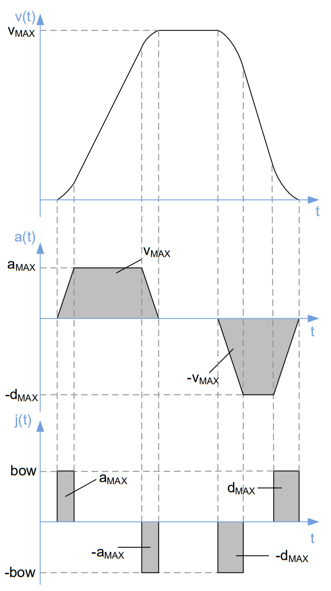
Figure 3. S-shaped velocity motion profile with linearly changed acceleration values and constant bow values (similar to the motion profile of TMC457 with bow_max > 0).
ADI Trinamic Motion Controller – Examples
The motion profiles which are introduced in chapter 2 are implemented in ADI Trinamic motion control integrated circuits. In the following, TMC429 and TMC457 and its motion profile parameters are introduced and explained.
TMC429 – Advanced trapezoidal velocity ramps
TMC429 is a miniaturized high performance stepper motor controller which controls up to three 2-phase stepper motors concurrently. The motor controller includes a motion controller which creates an trapezoidal velocity ramp.
The ramp mode ramp_mode has to be declared initially. Four modes are available. First, the default mode is the RAMP_MODE which provides positioning tasks. Second, the SOFT_MODE is similar to the previous mode except that velocity is reduced exponentially to reach the target position. This results in a soft, exponentially shaped velocity profile during deceleration phase which is similar to the S-shaped ramps (chapter 2.2.3) to reduce system vibrations at the target position. To drive stepper motors precisely with a constant velocity, the VELOCITY_MODE ramps the velocity to the requested value with user defined limits of velocity and acceleration. These limits are ignored in the HOLD_MODE which generates a motion profile from given velocities. That way the motion profile could be created completely by the connected microcontroller. To start positioning, the target position x_target have to be set differently to the current position x_actual. Both parameters may alter during positioning. The current velocity v_actual will be altered with a constant acceleration a_max to the user defined maximum velocity v_max. To finish positioning the current velocity will be reduced to 0 with a deceleration value which equals a_max. Exceptions to the pure trapezoidal velocity ramp (chapter 2.2.2) are explained in the following.
A minimum velocity value v_min could be set. If the current velocity is equal or smaller than this value during deceleration phase of the motion profile, the velocity could be stop abruptly if the target position is reached (see Figure 4a, 4b). This allows a faster positioning because the stepper motor is not slowed down this value until the x_target is reached. To ensure exact positioning, v_min should be greater than 1.
Due to the permanent calculation of v_target during positioning mode (RAMP_MODE, SOFT_MODE) deceleration phase could be started before maximum velocity is reached. As a result, a triangular motion profile is generated (see Figure 4b) fulfilling following equation which is a variation of (1):

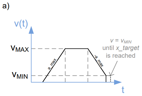
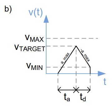
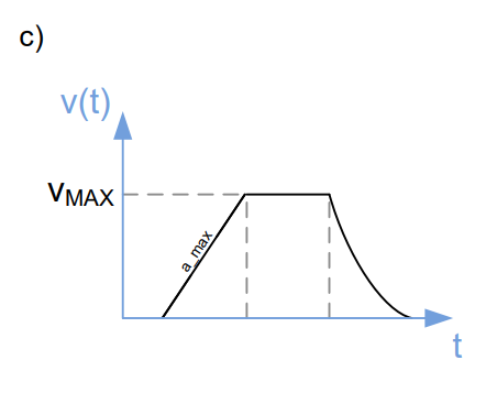
Figure 4 Velocity ramps of TMC429:
- Trapezoidal ramp with minimum velocity v_min to finish positioning
- Triangular ramp with minimum velocity v_min due to a small distance s
- SOFT_MODE: Trapezoidal ramp with exponentially shaped velocity during deceleration phase
TMC457 – S-shaped velocity ramps
To provide 2-phase stepper and piezo motors with a precise, fast and jerk-free motion profile, the TMC457 is a very good choice. This motion controller provides besides a highly customizable S-shaped velocity ramp, trapezoidal ramps as well with the opportunity to alter all ramp parameters during motion. Three ramp_modes are available: positioning mode, velocity mode and hold mode. These modes correspond to the modes RAMP_MODE, VELOCITY_MODE and HOLD_MODE of the TMC429. The positioning mode starts also by setting x_target ≠ x_actual and appropriate parameters for velocity, acceleration and bow. The deceleration parameter d_max could differ from the acceleration parameter a_max. If both parameters are equal, parameter a_max_d_max sets both to the same value. By setting the jerk parameter bow_max to an integer value which is larger than 0, a S-shaped velocity ramp – similar to the ramp depicted in Figure 3 – is calculated to reach precisely x_target. If bow_max = 0, a trapezoidal ramp is generated (Figure 2) which could be triangular if the maximum velocity v_max is not reached.
The parameter v_target has to be set appropriately to perform the other ramp modes. This specified velocity value is set immediately for the motor without considering any ramp parameter (hold mode) or a corresponding S-shaped or trapezoidal velocity ramp is created to reach this value with a motion profile depending on bow_max, a_max and d_max (velocity mode).
Bow parameter for TMC457 is given as logarithmic values. A double bow leads to half the time to reach a certain acceleration.
| 0 | The ramp generator uses trapezoid ramps. This corresponds to an infinite bow value. |
| 1 to 18 | Bow for s-shaped ramps in logarithmic representation. A high bow value leads to a shorter bow phase. The bow_value is added with 1/1024 fCLK[Hz] to acceleration a_actual up to the value set by a_max for acceleration resp. d_max for deceleration. bow_value = 2^(bow_index-1) bow_index = 1, 2, 3, …, 18 ⇔ bow_value = 1, 2, 4, …, 262144 Attention on bow setting: The resulting bow_value must not exceed A_MAX or D_MAX setting. Otherwise oscillations may result. Example: With bow=18, never set A_MAX to or below 262144. |
Units of velocity, acceleration and bow for the TMC457
| v_max | Maximum velocity for positioning mode. | 0 to $7FFF0000 for any a_max[µsteps / t] |
| v_target | Target velocity The sign determines the direction in velocity mode and hold mode. |
± $7FFF0000 for any a_max[µsteps / t] |
| a_max | Acceleration, unsigned fixed point 16.8 representation | 0 to $FFFFFD [µsteps / t^2] |
| d_max | Deceleration parameter, unsigned Fixed point 16.8 representation The effective deceleration with s-ramp enabled is 15/16 of d_max |
0 to $FFFFFD [µsteps / t^2] |
| d_stop | Deceleration for stop event, for security reason it is with bow = 0 | [µsteps / t^2] |
| bow_max | S-Ramp configuration 0=linear ramp (trapezoid) bow_index = 1, 2, 3, …, 18 ⇔ bow_value = 1, 2, 4, …, 262144 |
bow_value [µsteps / t^3] |
Conversion of the TMC457 units to real world units
The units of a TMC457 register content are written as register[457].
| Parameter vs. Units | ||
| Parameter / Symbol | Unit | calculation / description / comment |
| fCLK[Hz] | [Hz] | clock frequency of the TMC457 in [Hz] |
| s | [s] | second |
| US | microstep | |
| FS | fullstep | |
| velocity v[Hz] | microsteps / s | v[Hz] = v[457] * ( 2 * fCLK[Hz] / 2^31 ) |
| acceleration a[Hz/s] | microsteps / s^2 | a[Hz/s] = a[457] * fCLK[Hz]^2 / (16*256) / 2^30 |
| bow [Hz/s2] | microsteps / s^3 | b[Hz/s2] = bow_value * fCLK[Hz]^3 / (16*256) / 2^30 / 1024 |
| micro step resolution USR (used U instead of µ for micro) |
counts | micro step resolution in number of microsteps (i.e., the number of microsteps between two fullsteps) |
| v[FS] @ USR | US/s | v[FS/s] = v[US/2] / USR USR ⇔ microstep resolution |
| a[FS/^2] @ USR | US/s^2 | a[FS/s^2] = a[US/s] / USR |
| ramp_steps[457] = rs | [457] | rs = 2 * (v[457])^2 / (a[457]) / 2^18 micro steps during linear acceleration ramp (if v_max is really reached during acceleration) |
General hint for selection of bow value:
The ramp generator is the heart of the motion controller. It runs either ramp with linear velocity profile or ramp with s-shape velocity profile. The selection is done by the bow parameter. Setting bow to 0 selects linear velocity profile. Linear ramps perform the quickest motion, by using the maximum available acceleration at all times. But since the acceleration becomes switched on and off abruptly, system resonances can occur. They appear like an additional load on the motor, thus reducing the available useful portion of motor torque. Further, system resonances need some time to fade away, and this can cost valuable system time if a complete stand still is required before other actions can start. With the S-shaped ramp, resonances can be reduced. However, it is advised to choose the bow parameter as high as possible, in order to optimize positioning time.
Motion Controller Registers vs. TMCL Parameters
On TMCM modules that are equipped with a TMC429 or TMC457 motion controller, most of the motion controller registers mentioned in this application note are directly mapped to TMCL parameters. On TMC429 based modules, these are mapped as follows:
| Register | TMCL axis parameter |
| v_max | 4 (maximum positioning speed) |
| v_target | 2 (target velocity), ROL/ROR command parameter value |
| v_actual | 3 (actual velocity) |
| x_target | 0 (target position), MVP command parameter value |
| x_actual | 1 (actual position) |
| a_max | 5 (max. acceleration) |
Selection of the mode (RAMP_MODE, VELOCITY_MODE) is done automatically by the ROL/ROR, MVP and MST commands.
The following table shows the parameter mapping on modules equipped with a TMC457 (currently these are only the TMCM-142 and PD-146 modules):
| Register | TMCL axis parameter |
| v_max | 4 (maximum positioning speed) |
| v_target | 2 (target velocity), ROL/ROR command parameter value |
| a_max | 16 (max. acceleration) |
| d_max | 17 (max. deceleration) |
| d_stop | 15 (stop deceleration) |
| bow_max | 18 (max. bow) |
| X_target | 0 (target position), MVP command parameter value |
| X_actual | 1 (actual position) |
Selection of the mode (RAMP_MODE, VELOCITY_MODE) is done automatically by the ROL/ROR, MVP and MST commands. TMCL parameter 5 sets both acceleration and deceleration to the same value. On TMC457 based modules it is also possible to select PPS units instead of internal units using the command SAP 255, 0, 1.
